Stress Manipulation
Derive results based on the effective stress or selected stress type.
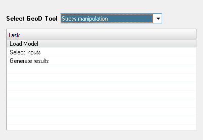 Figure 1.
 Note:
- It is recommended that the input file contains effective stress results.
- The model and results file must have Abaqus naming conventions e.g.
*.odbor*.h3dfile created using the Results Conversion tool. - The loading of the model and result files can be done either before or after the launching of the tool.
Stress Manipulation
-
Select the Stress
Manipulation tool from the Select GeoD Tool drop down list.
 Figure 2.
 -
Click the Load Model from the Task table.
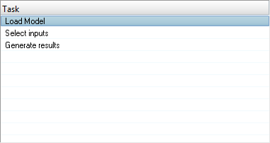 Figure 3.
 -
Click Select inputs task.
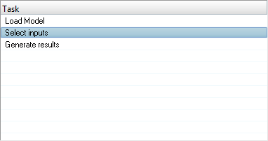 Figure 4. The Select inputs panel is displayed.
 Figure 5.
 -
Click the Select All
 button.
All available subcases in the table are selected.
button.
All available subcases in the table are selected. -
Click the Select None
 button.
All subcases are deselected.
button.
All subcases are deselected. -
Click the Select Reverse
 button.
Subcase selection is reversed.
button.
Subcase selection is reversed. -
Select the required simulation from the Simulation table.
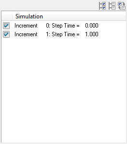 Figure 6.
 -
Select the required stress components from the Derive Results Based On
table.
 Figure 7. Note: By default, the global stress with IP-Effective (Integration Point) is selected. The user can select any one stress type for deriving additional results.
 -
Select the required results from the Results to Propagate table to propagate into the new h3d
file.
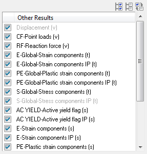 Figure 8. Note: The user can propagate the results from ODB file to H3D file by selecting the results from the Results to Propagate table. Uncheck the results that are not required to be propagated (copied) into the new h3d file.
 -
Click the Components button.
The Extended Entity Selection window is displayed.
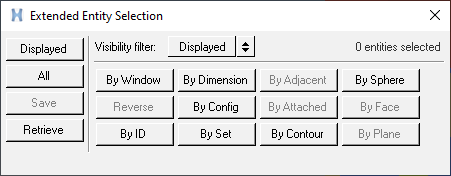 Figure 9.
 -
Click the Displayed button adjacent to the Components button.
 Figure 10. The components is highlighted in the graphics area.
 -
Click Clear
Collector
 to reset or clear the component
selection.
to reset or clear the component
selection.
-
Select the required results from the Standard
Results table.
 Figure 11. Note: By default the Principal stress is selected.
 -
Select the required results from the Derived
Scalars table.
 Figure 12. Note: By default the Mean Stress stress is selected.
 -
Select the required results from the In-Plane from
Tensor table.
 Figure 13.
 -
Select the required ratios from the Ratios table.
 Figure 14.
 -
Click the file browser button
 in the Output file text field.
A file selection window opens.
in the Output file text field.
A file selection window opens. -
Click Generate H3D.
An information message is displayed.
 Figure 15. Note: The H3D file is generated using HV Trans result translator.Once the H3D file is generated, a confirmation window is displayed.
 Figure 16.
 -
Load the newly created h3d file, after the completion of the process into
HyperView window along with the other propagated results.
 Figure 17.