Planar Results (Volumetric)
The purpose of this tool is to calculate and derive the normal stress and shear stress for imaginary 2D plane(s; faults/fractures) within a 3D volume.
Note:
- The results file with the 3D volume mesh and matching results is supported as inputs to calculate planar results (volumetric) tool.
- The results types under Derive Results Based On are filtered based on the
configuration in the
planar_derived_resulttype_filters.txt. - Before launching the tool, load the model and the result files. If you
launch the tool before loading the required files, the following message is
displayed.
 Figure 1.
-
Select the Planar Results
(volumetric) tool from the Select GeoD Tool drop down list.
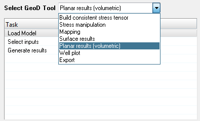 Figure 2.
 -
Click the Load Model from the Task table.
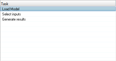 Figure 3.
Select inputs
-
Click Select inputs.
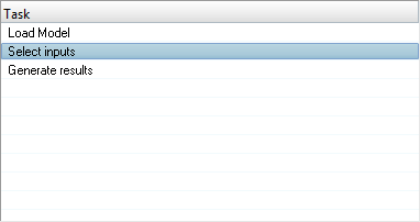 Figure 4. The Select inputs panel is displayed.
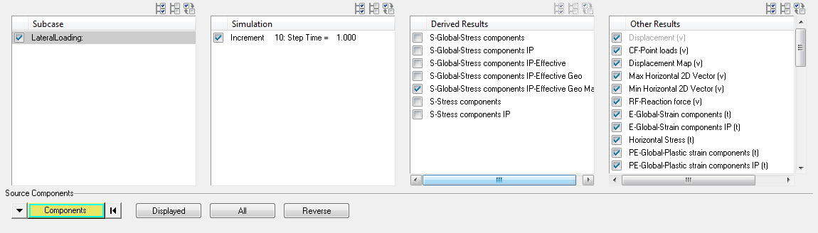 Figure 5.
 -
Click the Select All
 button.
All available subcases are selected.
button.
All available subcases are selected. -
Click the Select None
 button.
All subcases are deselected.
button.
All subcases are deselected. -
Click the Select Reverse
 button.
Subcase selection is reversed.
button.
Subcase selection is reversed.
Simulation
-
Select the required simulation(s) from the Simulation table.
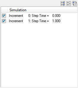 Figure 6.
Derived Results
-
Select the required results from the Results to Propagate table to propagate (copy) into the new h3d
file.
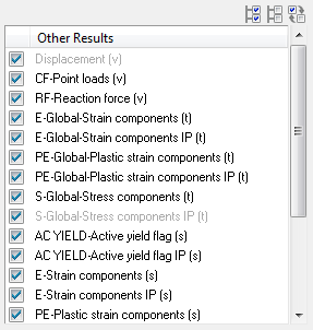 Figure 7. Note: You can propagate the results from source file to target h3d file by selecting the results from the Results to Propagate table. Uncheck the results that are not required to be propagated into the new h3d file.
Components
-
Click the Components button.
Extended Entity Selection window opens.
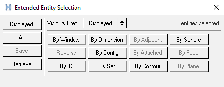 Figure 8.
 -
Click the Displayed button adjacent to the Components button.
 Figure 9. The components are highlighted in the graphics area.
 -
Click Clear
Collector
 , to reset or clear the component
selection.
, to reset or clear the component
selection.
Fracture Set
-
Enter the values in the Dip
(deg: inclined from horizontal/00) and Dip
Direction (deg: clockwise from North/000) fields and press
enter.
The normal corresponding to the imaginary plane is defined in the Normal to Plane field.
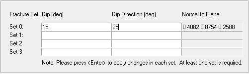 Figure 10.
 -
After defining the required inputs, click the file browser button
 in
the Output file text field.
A file selection window opens.
in
the Output file text field.
A file selection window opens. -
Click Generate H3D.
A new H3D file will be written containing the normal and shear stresses on the imaginary planes defined. An information message is displayed.
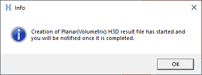 Figure 11.
 -
Once the H3D file is generated, a confirmation window opens.
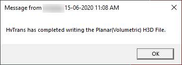 Figure 12.