Exercise 5: Troubleshoot Failure of Connectors to Realize

In this exercise, you will become familiar with troubleshooting the failure of connectors to realize. This exercise will help you identify issues related to small projection tolerance and missing link definitions.

In this exercise, you will realize connectors to weld parts of a vehicle door frame. The model is depicted in Figure 1.


Figure 1.

Retrieve and View the Model File

In this step, you will retrieve and view the model file in HyperMesh.

  1. Start HyperMesh Desktop.
  2. In the User Profile dialog, set the user profile to LsDyna.
  3. Open a model file by completing one of the following options:
    • Click File > Open > Model from the menu bar.
    • Click on the Standard toolbar.
  4. In the Open Model dialog, open the body_side_assembly.hm file.
  5. Observe the model using various visual options available in HyperMesh (rotation, zooming, and so on).

Realize the Connectors

In this step, you will realize the connectors using a projection tolerance of 1.0.

  1. Open the connector Spot panel by clicking Connectors > Realize > Spots from the menu bar.
  2. Click location: connectors > all.
  3. Click type = and select mat100.
  4. In the tolerance =, enter 1.0.
  5. Click realize.
    Note: The Status bar reads, "257 connectors realized (9 failed)".
    HyperMesh realizes the selected connectors into LS-DYNA 100 Mat100 (beam) welds.
  6. Click return.

Review the Information Table and Determine Reasons for Failure

In this step, you will review the information table listing the connectors that failed to realize and determine the reasons for failure.

  1. On the Visualization toolbar, click .
  2. In the Visualization tab, click .
  3. Under State, clear the Realized checkbox.
    The display of the realized (green) connectors turns off.


    Figure 2.
  4. Open the Connector Browser by clicking View > Browsers > HyperMesh > Connector from the menu bar.
  5. In the Connector Entity Browser, review the five red connectors with the IDs: 96, 155, 223, 261, and 262.
    Note: In the Layer column, 2 layers are specified, and in the Link1 and Link2 columns, a link is defined. Because the number of layers and links that were defined match, a possible cause for the connectors not realizing is a small projection tolerance.
  6. Review the four connectors with the IDs: 152, 153, 154, and 156.
    Note: In the Layer column, 3 layers are specified. In the Link1 column, one link is defined; in the Link2 and Link3 columns, no links are defined. Because the numbers of layers and links do not match, the likely cause for the connectors not realizing is undefined link definitions.

Realize the Failed Connectors

In this step, you will realize the failed connectors using a larger projection tolerance.

  1. In the Connector Entity Browser, right-click and select Create > Spot from the context menu.
  2. Click location: connectors > displayed.
  3. Click type = and select mat100.
  4. In the tolerance = field, enter 2.0.
  5. Click realize.
    Note: The Status bar reads, "5 connectors realized (4 failed)".
    HyperMesh realizes the selected connectors into LS-DYNA 100 Mat100 (beam) welds.

Define the Missing Second Link for the Failed Connectors

In this step, you will define the missing second link for the failed connectors.

  1. In the Connector Entity Browser, select the four red, unrealized connectors.
    Tip: Select multiple connectors by pressing Ctrl while left-clicking on connectors.
  2. Right-click on the selected connectors and select Add Link from the context menu.
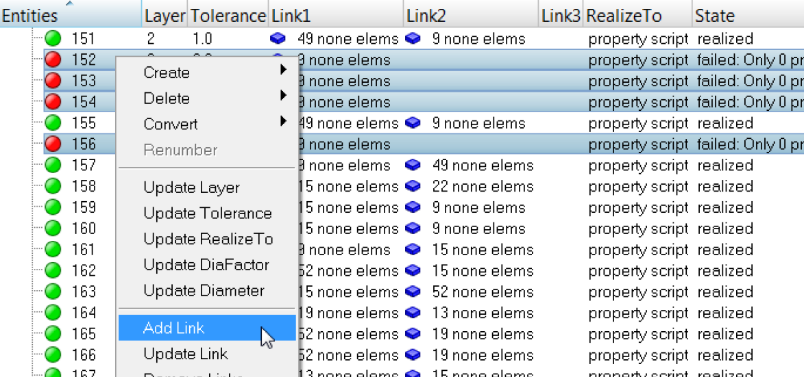

    Figure 3.
  3. In the Add Link window, set Link Type to Components.


    Figure 4.
  4. Set Links to Select.
  5. Under Links, for Entities, click 0 Component > comps.


    Figure 5.
  6. In the panel area, click comps.
  7. Select the component, Comp2.
  8. Click select.
  9. Click proceed.
  10. At the top of the Add Links window, click Add.
  11. In the confirm dialog, click Add Link.
    HyperMesh adds the specified link entity to the connector.

Realize the Failed Connectors

In this step, you will realize the failed connectors.

For this step, you should remain in the realize subpanel of the Spot panel.
  1. Click location: connectors > displayed.
  2. Click type = and select mat100.
  3. In the tolerance =, enter 4.0.
  4. Click realize.
    HyperMesh realizes the selected connectors into LS-DYNA 100 Mat100 (beam) welds.
  5. On the Visualization toolbar, click .
  6. In the Visualization tab, click .
  7. Under Color by, select State.
  8. Under State, select the Realized checkbox.
    Note: All of the connectors are realized into FE elements.
    HyperMesh displays all of the connectors, which are green.

Save Your Work

In this step, you will save your work in HyperMesh.

This exercise is complete.
Save your work as a HyperMesh file.