Exercise 1: Weld Between Geometry Surfaces and Shell Elements
In this exercise, you will become familiar with creating welds at pre-defined weld
points between geometry surfaces and shell elements.
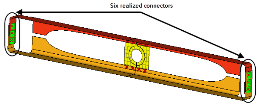
In this exercise, you will first weld the two front trusses
depicted in Figure 1 by creating
connectors between the geometry surfaces at pre-defined weld points and realizing the
connectors into two node weld elements. Second, you will weld the two front trusses to
the reinforcement plate depicted in Figure 2 by creating connectors between their shell elements at pre-defined
weld points and realizing the connectors into two node weld elements. Figure 1. Figure 2.
Retrieve and View the Model File
In this step, you will retrieve and view the model file in HyperMesh.
Start HyperMesh Desktop.
In the User Profile dialog, set the user profile to
LsDyna.
Open a model file by completing one of the following options:
Click File > Open > Model from the menu bar.
Click on the Standard
toolbar.
In the Open Model dialog, open the
frame_assembly_1.hm file.
On the Visualization toolbar, click to shade your model's geometry and surface edges.
Observe the model using various visual options available in HyperMesh (rotation, zooming, and so on).
Figure 3.
Create Welds Between the Geometry
In this step, you will create welds between the geometry for the two front trusses at
the pre-defined weld points.
In the Model Browser, verify that the current component is
Con_Frt_Truss.
Tip: The current component is always boldfaced in the Model Browser, Component folder.
Open the connector Spot panel by clicking Connectors > Create > Connectors > Spots from the menu bar.
Set the location selector to points.
Select the six pre-defined weld points by clicking points > by collector.
Select the Con_Frt_Truss checkbox.
Figure 4.
Click select.
Double-click connect what: comps.
Select the Front_Truss_1 and
Front_Truss_2 checkboxes.
Click select.
In the tolerance= field, enter 5.
Click type= and select
weld.
Under the connect what selector, toggle from elems to
geom.
Figure 5.
Click create.
A green connector indicates that the creation of the weld entity was
successful. There are three states of connectors: realized (green), unrealized
(yellow), and failed (red). The color of the connectors can change from yellow
to green (if created manually), indicating they are realized into weld elements.
If you create connectors automatically, they will be green immediately as there
is no interim unrealized (yellow) state. Figure 6. HyperMesh also adds fixed points to the surfaces at the
ends of the weld elements to guarantee connectivity between the weld elements
and the shell mesh that will be created on the surfaces. Figure 7.
HyperMesh creates and realizes six spot connectors,
and organizes them as geometry (not elements) in the current component
collector, Con_Frt_Truss.
Click return.
Create A Shell Mesh
In this step, you will create a shell mesh on the front truss components of the
model.
Open the Automesh panel by completing one of the following:
Click Mesh > Create > 2D Automesh from the menu bar.
Press F12.
Open the size and bias subpanel.
Click surfs > by collector.
Select the Front_Truss_1 and
Front_Truss_2 checkboxes.
Click select.
In the elem size= field, enter 10.
Set the mesh type to mixed.
Set the elems to surf comp/elems to current comp toggle to elems to
surf comp.
Switch the mesh mode from interactive to
automatic.
Click mesh.
HyperMesh meshes the surfaces. Figure 8.
On the 3D View Controls toolbar, left-click on to zoom in on the area with a connector.
See how the fixed point created from the weld has ensured the mesh seeding
passes through the weld. Figure 9.
Click return.
Create Connectors
In this step, you will create connectors between the shell mesh for the front trusses
and the reinforcement plate at pre-defined points.
In this step you will create and realize the connectors
manually.
In the Model Browser, Component folders, right-click on
Con_Truss_Plate and select Make
Current from the context menu.
Open the connector Spot panel.
Open the create subpanel.
Set the location selector to points.
Click points > by collector.
Select the Con_Truss_Plate component.
Click select.
Set connect when to now.
Double-click connect what: comps.
Select the Front_Truss_1,
Front_Truss_2, and Reinf_Plate
components.
Click select.
Under the connect what selector, toggle from geom to
elems.
Figure 10.
Click create.
HyperMesh creates eight spot connectors at the
selected weld points, and organizes them into the current component collector,
Con_Truss_Plate. Figure 11.
Realize the Connectors into Weld Elements
In this step, you will realize the connectors into weld elements.
Open the realize subpanel.
Click location: connectors > by collector.
Select the Con_Truss_Plate component.
Click select.
Click type= and select
weld.
In the tolerance= field, enter 5.
Set the mesh independent/mesh dependent toggle to mesh
dependent.
Note: When mesh dependent is active, HyperMesh equivalences
the nodes if the realized finite element of the connector is coincident to a
node of the shell mesh it is being connected to. If there are no suitable
nodes present, this option partitions the mesh accordingly to ensure the
mesh seeding passes through the weld point.
Figure 12.
Click realize.
HyperMesh realizes the selected connectors into weld
elements. Figure 13.


 on the Standard
toolbar.
on the Standard
toolbar. to shade your model's geometry and surface edges.


 to zoom in on the area with a connector.
See how the fixed point created from the weld has ensured the mesh seeding passes through the weld.
to zoom in on the area with a connector.
See how the fixed point created from the weld has ensured the mesh seeding passes through the weld.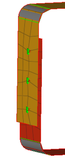

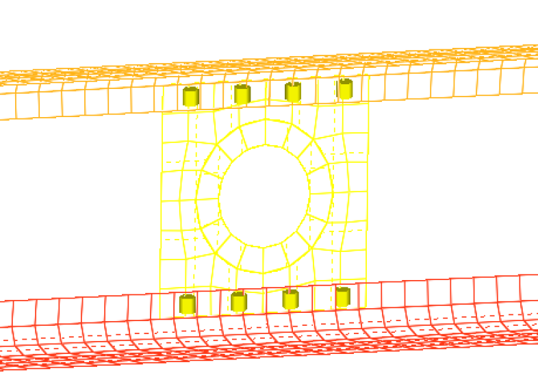
 Figure 12.