HM-4630: Interfacing for Arbitrary - Lagrangian - Eulerian Capability Using DYNA
In this step, you will become familiar with defining LS-DYNA cards related to the ALE capability. You will set up the model data for an LS-DYNA analysis of an ink cartridge falling through air and onto the ground.
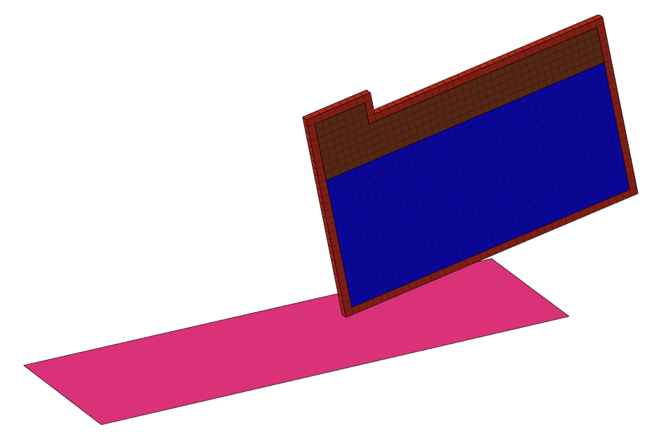
Figure 1.
Tools Overview
In this section, you will learn about the ALE setup panel, Card Edit feature, and the Control Cards panel.
ALE Setup Panel
The ALE setup panel can be accessed from the Analysis page. Use the ALE setup panel to create and modify input data pertaining to the Arbitrary-Lagrangian Eulerian LS-DYNA capability.
Card Edit Feature
The Card Edit feature can be accessed by clicking on the Collectors toolbar. Use the Card Edit panel to select the entities that are viewed in the card image subpanel. The card images are defined in the template file.
Access the Control Cards feature by clicking from the menu bar or by clicking Control Cards from the Analysis page.
Control Cards Panel
Use the Control Cards panel to set up job-level, solver specific data. The available Control Cards are defined in the template file.
Load the LS-DYNA Profile
In this step, you will load the LS-DYNA profile in HyperMesh.
- Start HyperMesh Desktop.
- In the User Profile dialog, set the user profile to LsDyna.
Retrieve and View the Model File
In this step, you will retrieve and view the model file in HyperMesh.
-
Open a model file by completing one of the following options:
- Click from the menu bar.
- Click
 on the Standard
toolbar.
on the Standard
toolbar.
-
In the Model Browser, expand the Component folder.
Notice the model is divided into four component collectors: AIR, CARTRIDGE, INK, and PLATFORM.
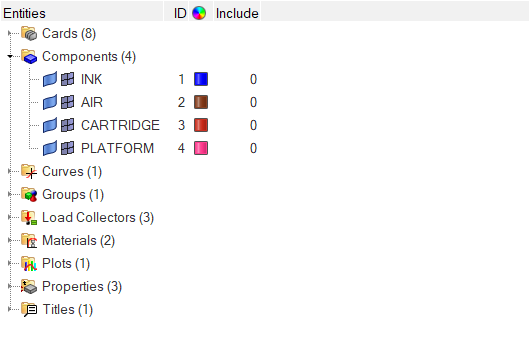
Figure 2.
Update the *SECTION_SOLID Card
In this step, you will update the *SECTION_SOLID card used by the ALE components INK and AIR to *SECTION_SOLID_ALE using three methods: Solver Browser, Model Browser, and Card Editor.
-
Method 1: Use the Solver Browser
-
Expand the *SECTION folder, expand the *SECTION_SOLID folder, and then
click SOLID PROP FOR ALE.
The Entity Editor opens, and displays the property's corresponding data.
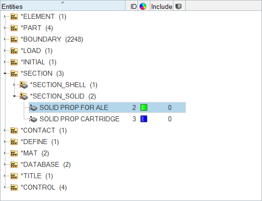
Figure 3.
-
Expand the *SECTION folder, expand the *SECTION_SOLID folder, and then
click SOLID PROP FOR ALE.
-
Method 2: Use the Model Browser
-
In the Model Browser, Property folder, click
SOLID PROP FOR ALE.
The Entity Editor opens and displays the property's corresponding data.
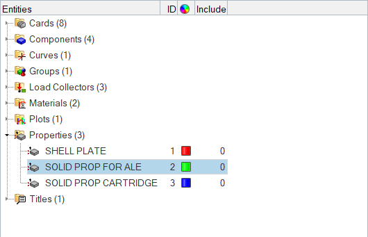
Figure 4.
-
In the Model Browser, Property folder, click
SOLID PROP FOR ALE.
-
Method 3: Use the Card Editor
-
In the Model Browser or Solver Browser, right-click on the property
SOLID PROP FOR ALE and select Card
Edit from the context menu.
The Card Image dialog opens.
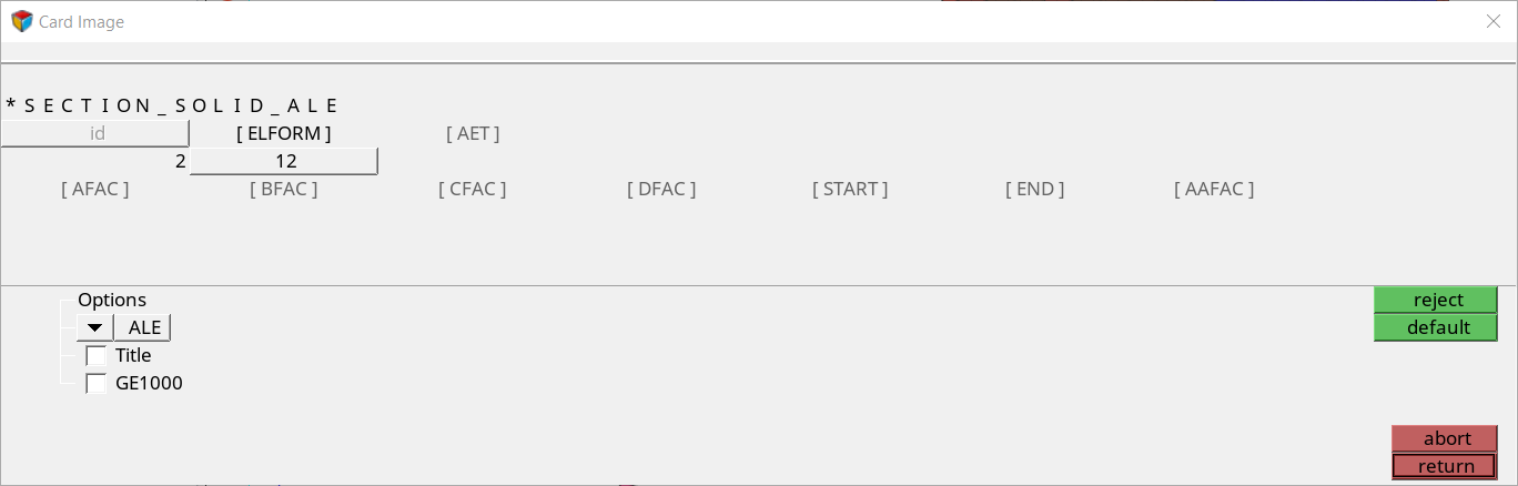
Figure 5.
-
In the Model Browser or Solver Browser, right-click on the property
SOLID PROP FOR ALE and select Card
Edit from the context menu.
Assign *EOS_LINEAR_POLYNOMIAL
In this step, you will assign *EOS_LINEAR_POLYNOMIAL for the ALE components.
-
For EOSID, click .
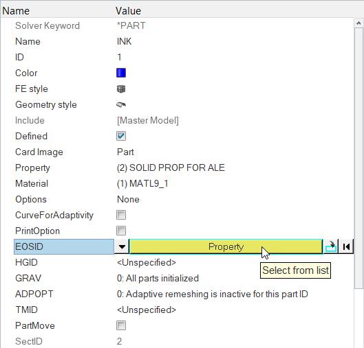
Figure 6. -
In the Select Property dialog, select
EOS_LINEAR and then click OK.
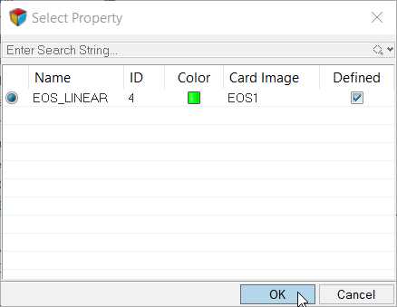
Figure 7.
Define *EOS_LINEAR_POLYNOMIAL
For this step, you will define *EOS_LINEAR_POLYNOMIAL for the ALE components.
-
In the Solver Browser, right-click and select from the context menu.
A new property opens in the Entity Editor.
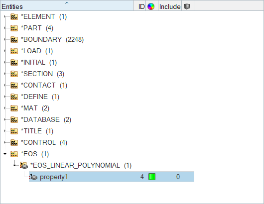
Figure 8.
Define *INITIAL_VOID_PART
In this step, you will define *INITIAL_VOID_PART to define the AIR component as the void in the fluid interaction.
Define *ALE_REFERENCE_SYSTEM_NODE
In this step, you will define *ALE_REFERENCE_SYSTEM_NODE to control the motion of the ALE mesh.
Define *ALE_REFERENCE_SYSTEM_GROUP
In this step, you will define *ALE_REFERENCE_SYSTEM_GROUP to specify the reference system type for the fluid interaction of the ALE components.
Review the *CONTROL_ALE Card
In this step, you will review the pre-defined *CONTROL_ALE card.
Export the Model
In this step, you will export the model to an LS-DYNA 971 formatted input file.
- From the menu bar, click .
- In the Import - Solver Deck tab, set Template to Keyword971.
- In the File field, navigate to your working directory and save the file as cartridge_complete.key.
- Click Export.
Submit the LS-DYNA Input File
In this step, you will submit the LS-DYNA input file to LS-DYNA 971.
- From the desktop’s Start Menu, open the LS-DYNA Manager program.
- From the solvers menu, select Start LS-DYNA analysis.
- Load the cartridge_complete.key file.
- Start the analysis by clicking OK.
View the Results in HyperView
The results for ALE data are stored as Extra Solid History Variable in HyperView.
Save Your Work
In this step, you will save your work as a HyperMesh file.