Exercise 2: Introduction to ANSYS Load Steps
In this exercise you will: create constraint load collectors; apply the constraints to the model; apply the force on mass elements with force1, force2, and force3 load collectors; create multiple load steps; add /SOLU and LSSOLVE in control cards; and export the deck to ANSYS *cdb format.
Load the ANSYS User Profile
In this step, you will load the ANSYS user profile in HyperMesh.
- Start HyperMesh.
- In the User Profile dialog, set the user profile to Ansys.
Retrieve the HyperMesh Model File
In this step, you will retrieve and open the model file.
- Optional:
If you model's elements and mesh lines are not shaded, click
 on the Visualization toolbar.

Figure 1.
Create a Constraints Load Collector
In this step you will learn how to create load collectors within HyperMesh.
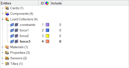
Figure 2.
Apply the Constraints to the Model
In this step, you will apply the constraints you created to the model.
-
Select the dof (degree of freedom) checkboxes as
indicated in Figure 3.

Figure 3. -
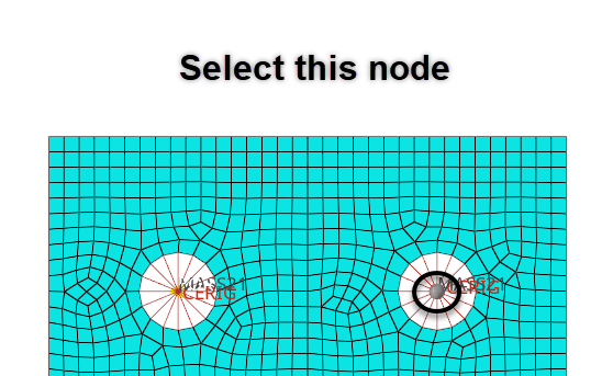
Select a start node and an end node on the left side of the model as indicated
in Figure 4.

Figure 4. -
Click Create.

Figure 5. -
Repeat steps 4 and 5 to select a start node and an end node on the
right side of the model as indicated in Figure 6.
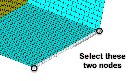
Figure 6. -
Click Create.

Figure 7. -
Click return to exit the Constraints panel.

Figure 8.
Apply the Force on Mass Elements with the Force1 Load Collector
In this step, you will apply the force on mass elements with the force1 load collector.
-
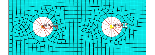
Select the two nodes in the center of the two bolt holes as indicated in Figure 9.
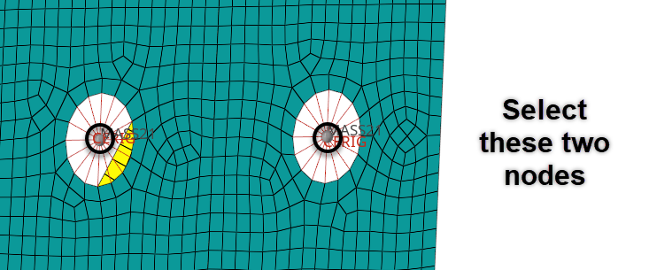
Figure 9. -
Click Create.

Figure 10. -
Click return to exit the Forces panel.
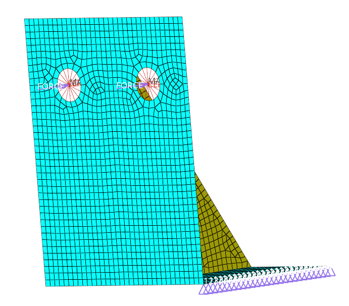
Figure 11.
Apply the Force on Mass Elements with the Force2 Load Collector
In this step, you will apply the force on mass elements with the force2 load collector.

Apply the Force on Mass Elements with the Force3 Load Collector
In this step, you will apply the force on mass elements with the force3 load collector.
-
Select the two nodes in the center of the two bolt holes as indicated in Figure 15.

Figure 15. -
Click create.
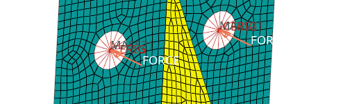
Figure 16. -
Click return to exit the Forces panel.
Figure 17.
Create Multiple Load Steps
In this step, you will create multiple load steps.
-
In the Model Browser, right-click and select from the context menu.
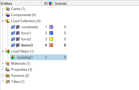
Figure 18.HyperMesh creates and opens a load step in the Entity Editor. -
For Loadcol IDs, click .

Figure 19. -
In the Select Loadcols dialog, select
constraints and force1.

Figure 20. -
In the Model Browser, review the Load Collectors and Load
Steps you created.

Figure 21.
Add /SOLU, ANTYPE, and LSSOLVE in the Control Cards
In this step, you will add the following Control Cards.
-
In the card image, click /SOLU
to exit the PREP7 preprocessor and enter the SOLU preprocessor.
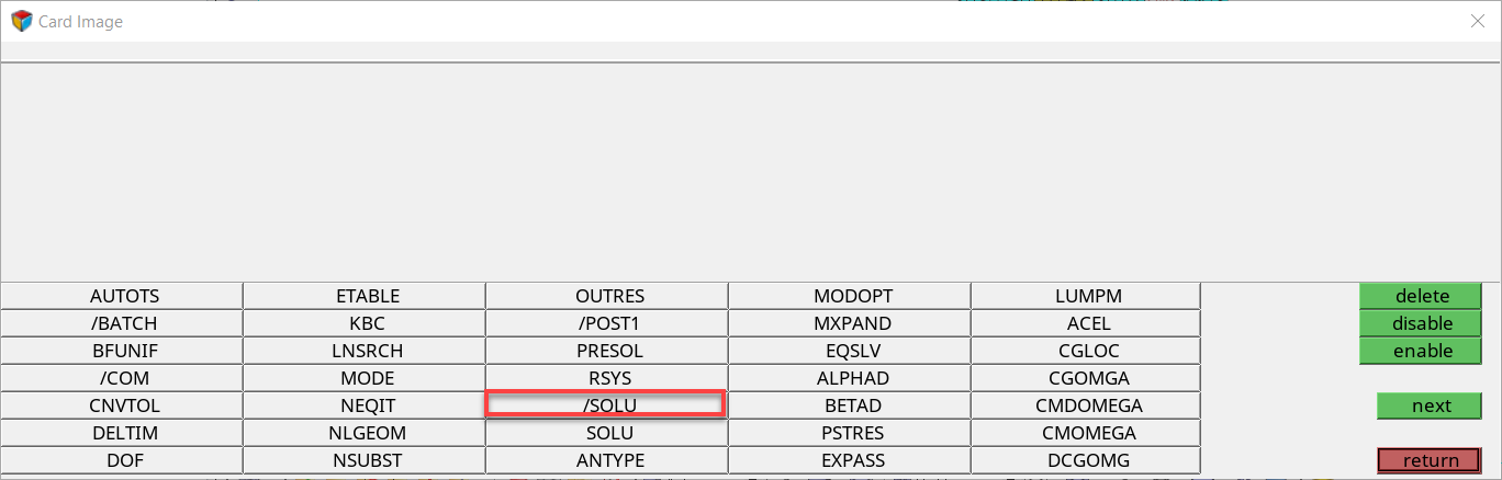
Figure 22. -
Click return.

Figure 23. -
Because you are solving the model for static analysis, click
ANTYPE.
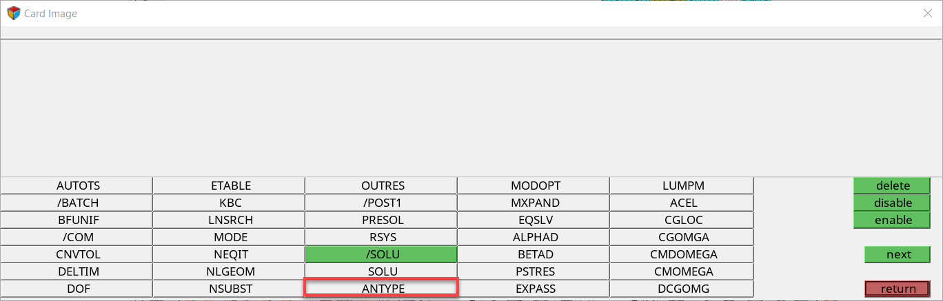
Figure 24. -
Set type to STATIC and status to
NEW.

Figure 25. -
Click LSSOLVE.

Figure 26.Tip: If you do not see the LSSOLVE Control Card, click next. -
Enter 1 in the LSINC field as indicated in Figure 27.
The load step increment is set.

Figure 27.
Export the Deck
In this step, you will export the deck to ANSYS *.cdb format.