HM-4430: Define ANSYS Contacts for Models in HyperMesh
In this tutorial you will learn how to set up surface to surface contacts and contacts manually.
Before you begin, it is recommended that you complete HM-1000: Getting Started with HyperMesh and Exploring the ANSYS Interface.
Also, copy hm-ansys_contact_manager_3-d_tutorial.hm from <hm.zip>/interfaces/ansys/ to your working directory.
Load the ANSYS User Profile
In this step you will load the ANSYS user profile in HyperMesh.
- Start HyperMesh Desktop.
- In the User Profile dialog, set the user profile to Ansys.
Retrieve the HyperMesh Model File
In this step, you will open a model file in HyperMesh.
-
If the load collector is displayed, in the Model Browser,
click
 next to the load collector to turn off the display
of its elements.
next to the load collector to turn off the display
of its elements.
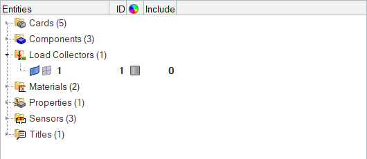
Figure 1. -
Fit the model to the graphics area by pressing F.
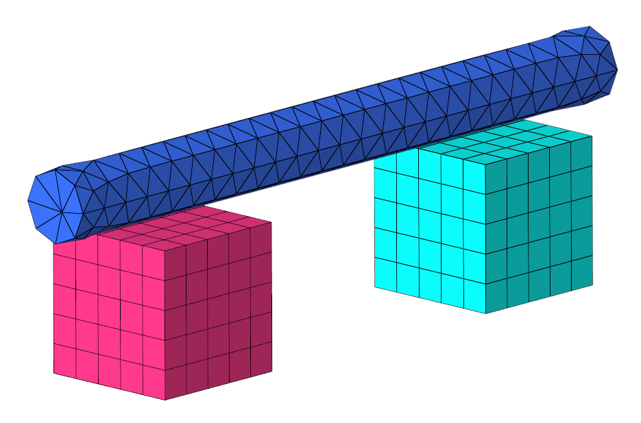
Figure 2.
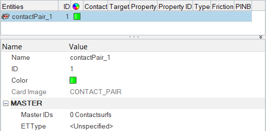
Create a Contact Pair
In this step you will create a contact pair in HyperMesh.
- In the second pane of the Contact Browser, right-click and select from the context menu.
Create and Attach a Contact Surface
In this step you, will create and attach a contact (master) surface in HyperMesh.
-
Mask the BOX_SOLID45 and CYLINDER_SOLID45 components in the first pane of the
Contact Browser.
- Right-click on the BOX_SOLID45 component.
- Select Hide from the context menu.
- Right-click on the CYLINDER_SOLID45 component.
- Select Hide from the context menu.
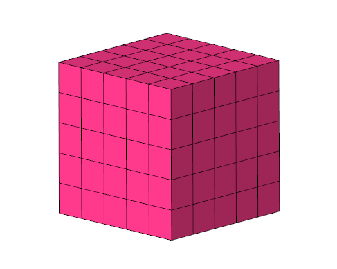
Figure 4. -
Create and attach a contact (master) surface.
-
In the Entity Editor, right-click on
Master IDs and select Create
Contact Surface using Elements from the context menu.
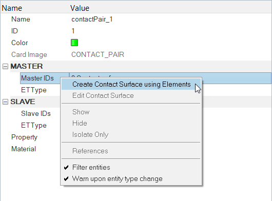
Figure 5. -
Set the advanced selection switch to
faces.
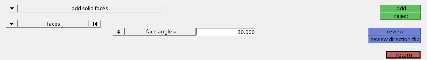
Figure 6. -
Select the top faces of the cube as indicated in Figure 7.
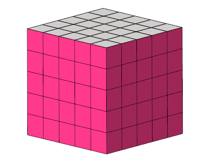
Figure 7. -
Observe the newly created contact surfaces.
By default, when contact surfaces are created over solid element faces, normals point outwards.
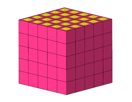
Figure 8.
-
In the Entity Editor, right-click on
Master IDs and select Create
Contact Surface using Elements from the context menu.
-
Create and attach an Et Type to the contact surface.
-
In theEntity Editor, under MASTER, right-click
on ETType and select
Create from the context menu.
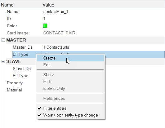
Figure 9. -
Close the dialog.
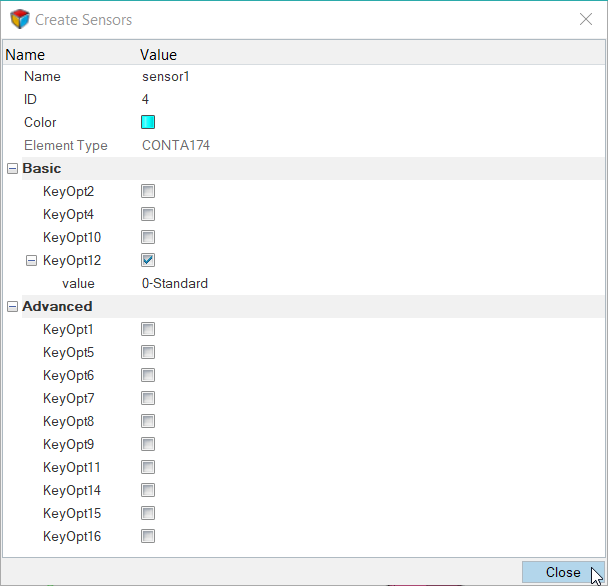
Figure 10.
-
In theEntity Editor, under MASTER, right-click
on ETType and select
Create from the context menu.
Create and Attach a Target Surface
In this step, you will create and attach a target surface in HyperMesh.
-
Unmask the CYLINDER_SOLID45 component.
- Right-click on CYLINDER_SOLID45 in the first pane of the Contact Browser.
- Select from the context menu.
-
Mask the BOX_SOLID95 component.
- Right-click on BOX_SOLID95 in the second pane of the Contact Browser.
- Select Hide from the context menu.
-
Mask the contactPair_1 contact surfaces.
- Right-click on contactPair_1 in the second pane of the Contact Browser.
- Select Hide from the context menu.
-
On the Standard Views toolbar, click
 to orient the model to the XY top plane view.
-
Create and attach a target (secondary) surface.
-
Set the advanced selection switch to
elems.
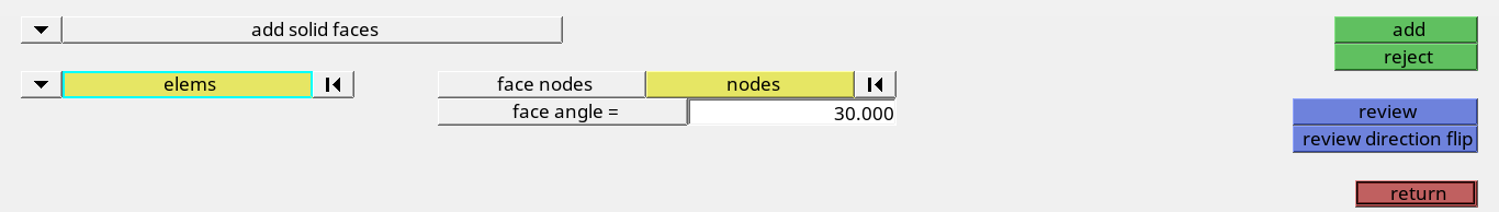
Figure 11. -
Select the elements indicated in Figure 12.
Tip: Quickly select elements with window selection by pressing Shift while clicking and dragging your mouse.
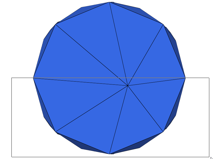
Figure 12. -
Using the nodes selector, select face nodes on the selected elements as
indicated in Figure 13.
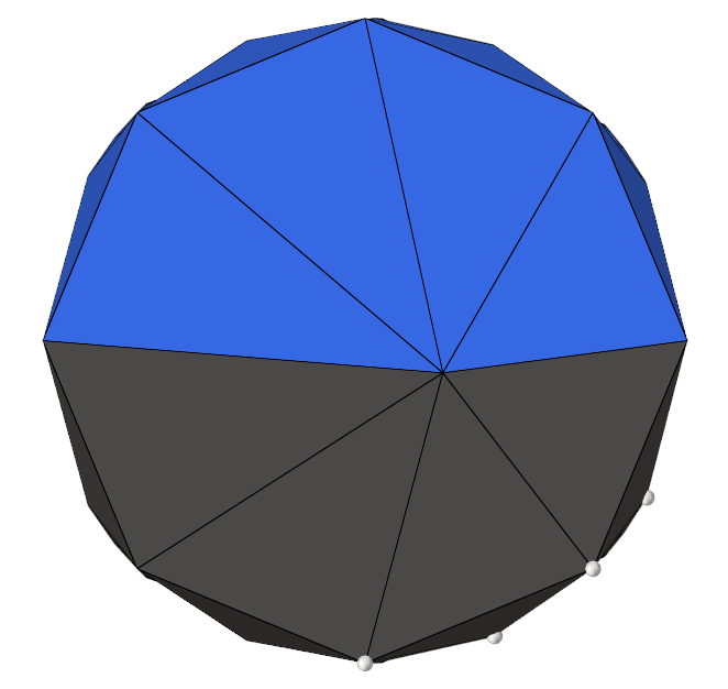 Figure 13.
 -
Click add.
Surfaces are created on selected elements.
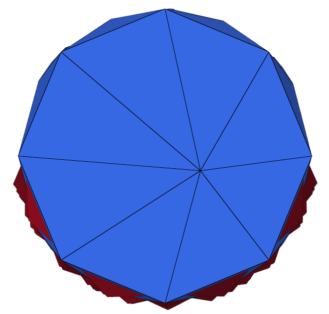
Figure 14.
-
Set the advanced selection switch to
elems.
-
Create and attach an Et Type to the contact surface.
Create and Attach a Property and Material to the Contact Pair
In this step, you will create and attach a property and material to a contact pair.
Review the Contact Pair
In this step, you will review the contact pair you created.
-
In the second pane of the Contact Browser, right-click on
contactPair_1 and select Isolate
Only from the context menu.
Only the main and secondary surfaces display.
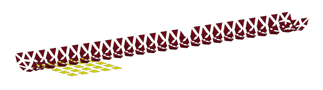
Figure 15. -
Right-click on contactPair_1 and select
Review from the context menu.
Contact regions display.
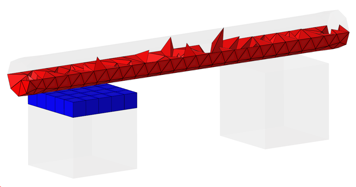
Figure 16.
Add /SOLU and SOLVE in the Control Cards
In this step, you will add the following Control Cards.
-
Click /SOLU to exit the PREP7 preprocessor and enter the
SOLU preprocessor.
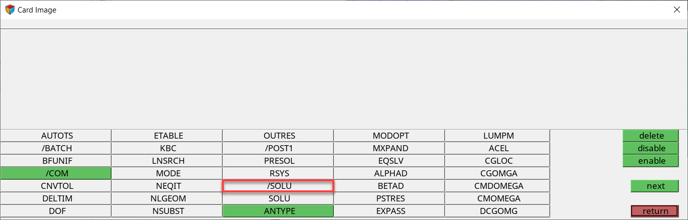
Figure 17. -
Click return.
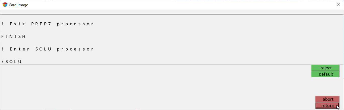
Figure 18. -
Click SOLVE.
Tip: If you do not see the SOLVE Control Card, click next.
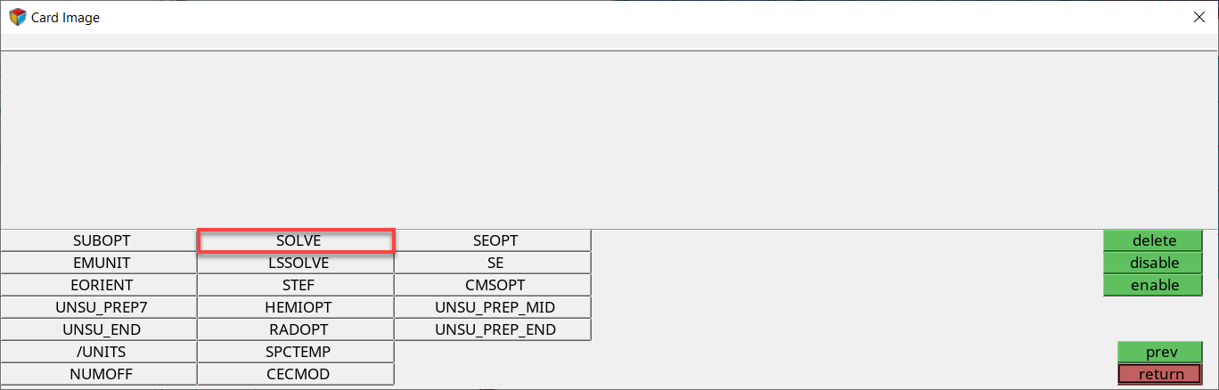
Figure 19.