HM-4420: Define ANSYS Contacts for Models in HyperMesh
In this tutorial you will learn how to set up edge to edge contacts, set up contacts manually, and create edge to edge contacts between circular and rectangular parts of a model.
Before you begin, it is recommended that you complete HM-1000: Getting Started with HyperMesh and Exploring the ANSYS Interface.
Also, copy the hm-ansys_contact_manager_2-d_tutorial.hm from <hm.zip>/interfaces/ansys/ to your working directory.
In HyperMesh, you can create contact pairs manually or with the Autocontact tool. The edge of the circular body acts as a Target (secondary) surface, and the top edge of the rectangular part acts as a contact (main) surface.
Load the ANSYS User Profile
In this step, you will load the ANSYS user profile in HyperMesh.
- Start HyperMesh Desktop.
- In the User Profile dialog, set the user profile to Ansys.
Retrieve the Model File
In this step, you will open a model file in HyperMesh.
- Optional:
If the load collector is displayed, click
 in the Model Browser next to
the load collector to turn off the display of the element.
in the Model Browser next to
the load collector to turn off the display of the element.
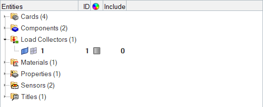
Figure 1. -
Fit the model to the graphics area by pressing F.
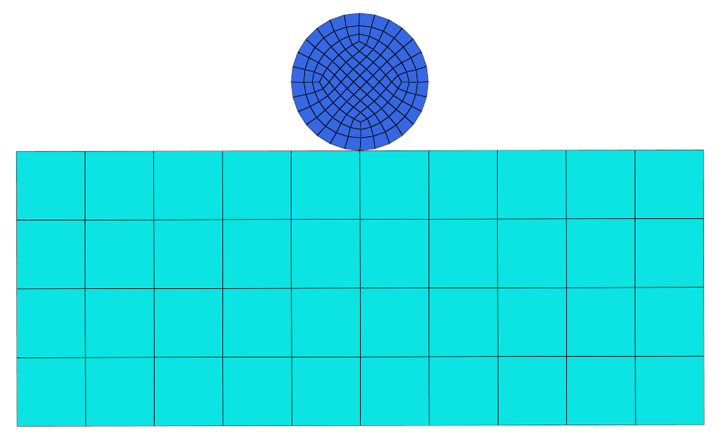
Figure 2.
Open the Contact Browser
In this step, you will open the Contact Browser in HyperMesh.
Create Target (Secondary) Surface
In this step, you will create a target surface in HyperMesh.
-
In the first pane of the Contact Browser, right-click and
select from the .context menu
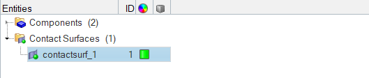
Figure 3.HyperMesh creates and opens a contact surface in the Entity Editor. -
For Elements, click .
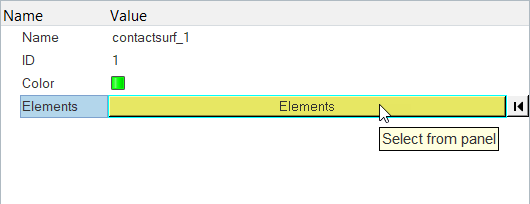
Figure 4. -
Set the entity selector to elems, then select the free
edges indicated in Figure 5.
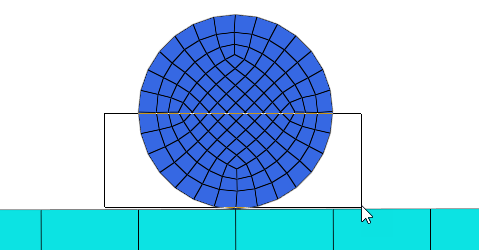
Figure 5.Tip: Quickly select elements with window selection by pressing Shift while clicking and dragging your mouse. -
Use the nodes selector to select two nodes along the free edges you selected in
step 7.
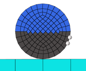
Figure 6. -
Click Add.
All of the edges of the selected elements are added to the surface.

Figure 7.
Create Contact (Master) Surface
In this step, you will create a contact surface in HyperMesh.
-
Set the entity selector to free edges, then select the
top free edges of the rectangular box as indicated in Figure 8.
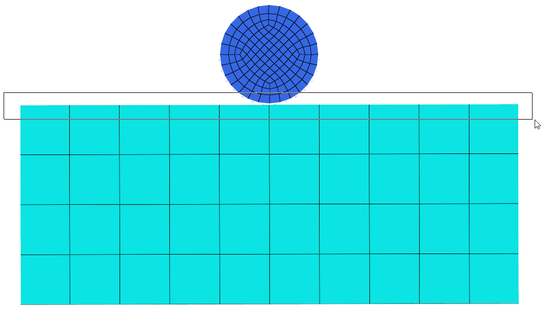
Figure 8. -
Click add.
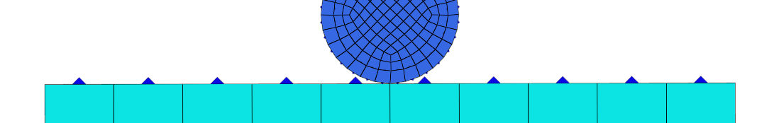
Figure 9.Surfaces are created on the top edge of the rectangular box.
Create a Contact Pair
In this step, you will create a contact pair.
-
In the second pane of the Contact Browser, right-click and
select from the context menu.
HyperMesh creates and opens a contact pair in the Entity Editor.
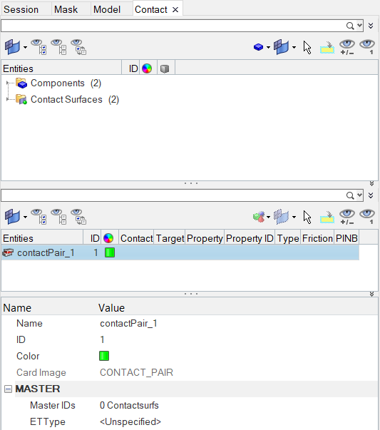
Figure 10. -
Attach the contact (master) surface.
-
For Master IDs, click .
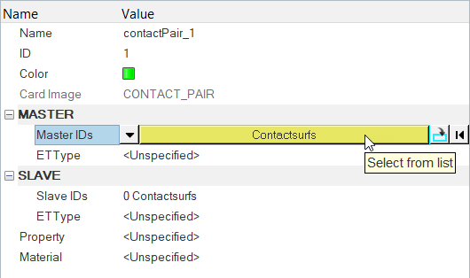
Figure 11. -
In the Select Contactsurfs dialog, select
contactsurf_2 and click OK.
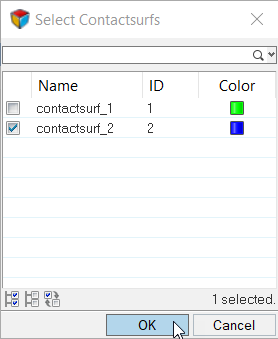
Figure 12. -
Under MASTER, right-click on ETType, and select
Create from the context menu.
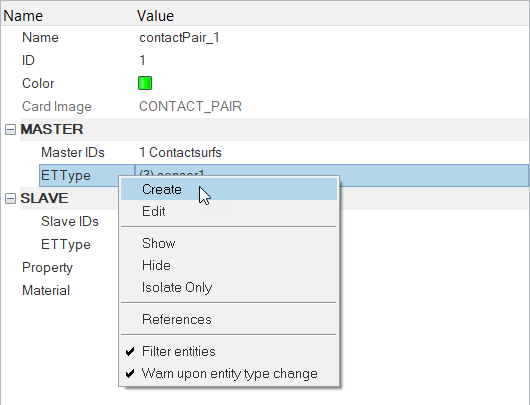
Figure 13. -
Click Close.
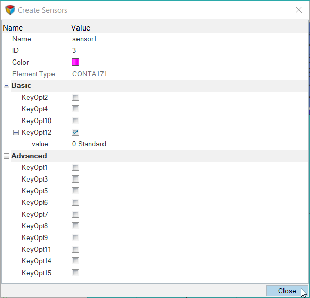
Figure 14.
-
For Master IDs, click .
Review the Contact Pair
In this step, you will review the contact pair you created in step Create a Contact Pair.
-
Right-click on the contact pair and select to review the contact area.
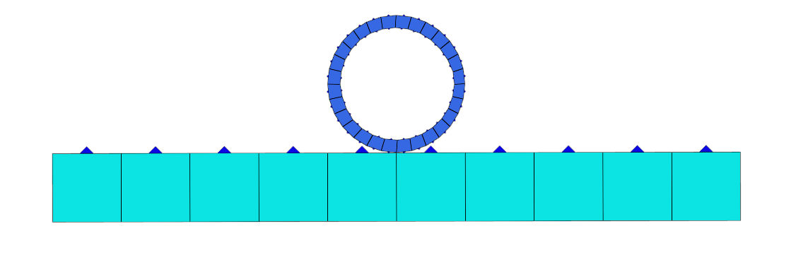
Figure 15.
Add /SOLU, ANTYPE, and SOLVE in the Control Cards
In this step, you will add the following Control Cards.
-
To exit the PREP7 preprocessor and enter the SOLU preprocessor click
/SOLU.
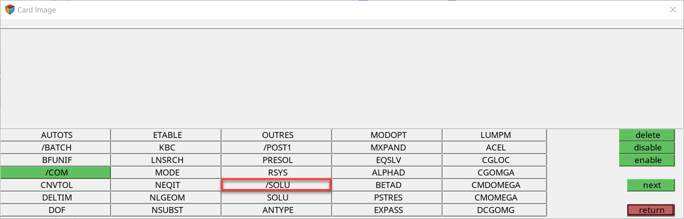
Figure 16. -
Click return.
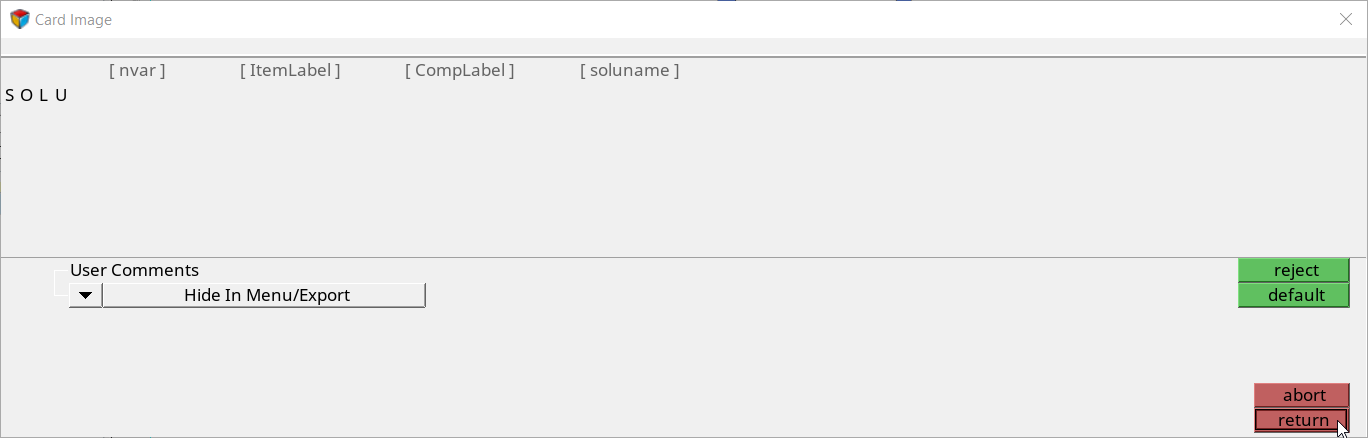
Figure 17. -
Since you are solving the model for static analysis, click
ANTYPE.
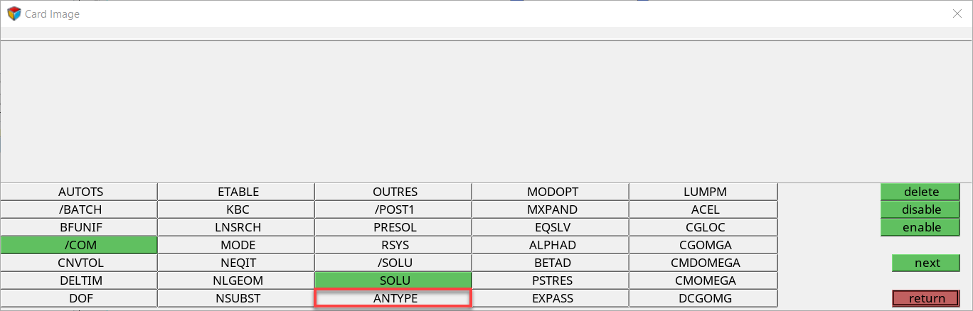
Figure 18. -
Set type to STATIC and status to
NEW.
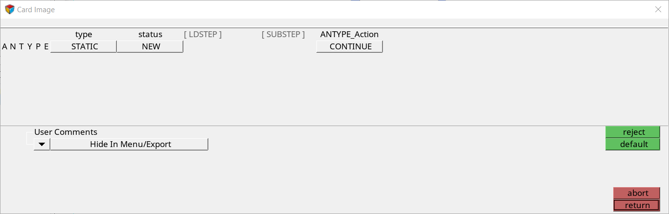
Figure 19. -
Click SOLVE.
Tip: If you do not see the SOLVE Control Card, click next.
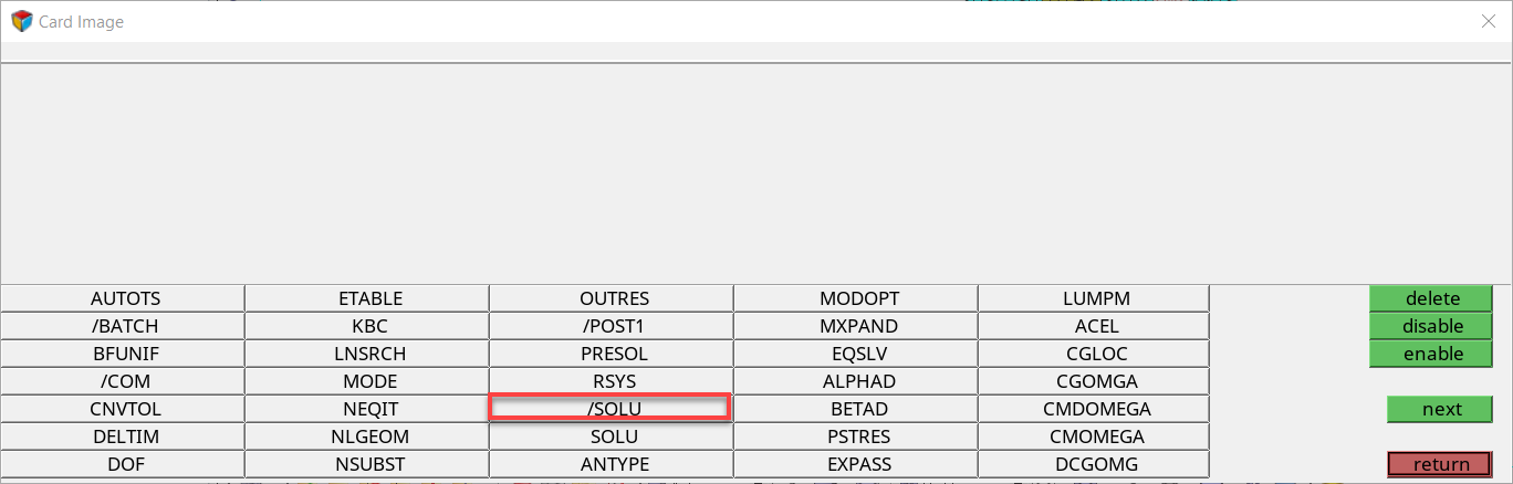
Figure 20.