HM-4450: Introduction to HyperBeam
In this tutorial, you will learn how to couple degrees of freedom and to assign a standard beam section using the Section and HyperBeam panels.
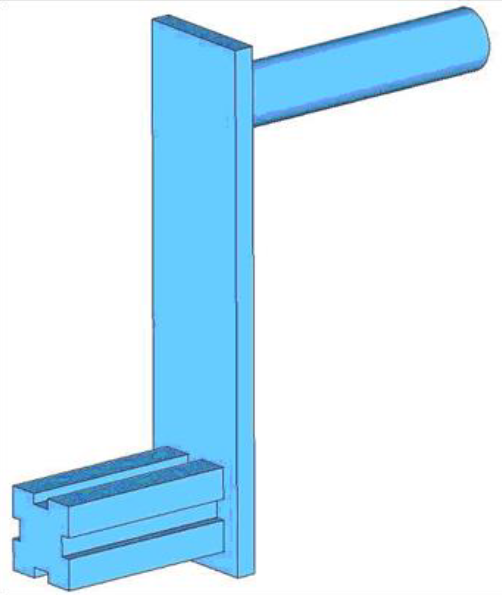
Figure 1.
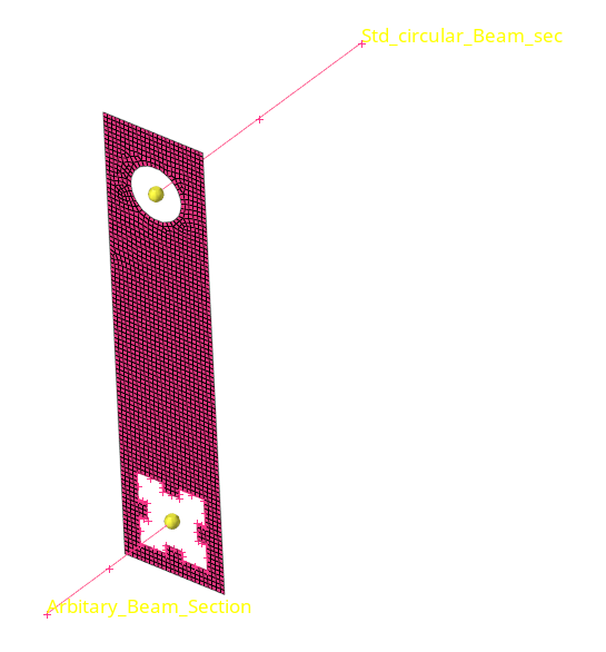
Figure 2.
Load the ANSYS User Profile
In this step, you will load the ANSYS user profile in HyperMesh.
- Start HyperMesh Desktop.
- In the User Profile dialog, set the user profile to Ansys.
Retrieve the Model File
In this step, you will retrieve and open the model file in HyperMesh.
-
In the Open Model dialog, open the
chapter3.hm file.
This model contains a plate collector which includes shell elements. The plate component is updated with the necessary element type, real constant, and material properties.
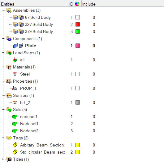
Figure 3.The model displays in the graphics area. - Optional:
If your model's elements and mesh lines are not shaded, click
 on the Visualization toolbar.
Create Collectors and Attach Element Types and Materials
In this step, you will create collectors and attach element types and materials to the collectors.
-
In the Model Browser, right-click and select from the context menu.
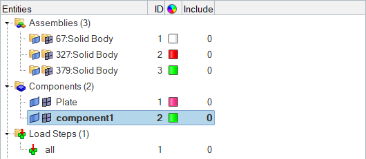
Figure 4.HyperMesh creates and opens a component in the Entity Editor. -
Right-click on Type and select
Create from the context menu.
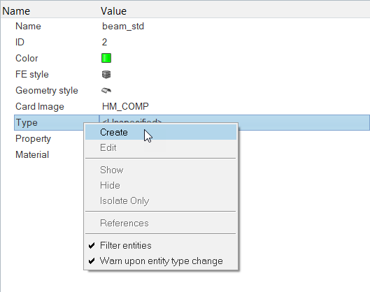
Figure 5.The Create Sensors dialog opens. -
Set Element Type to BEAM188.
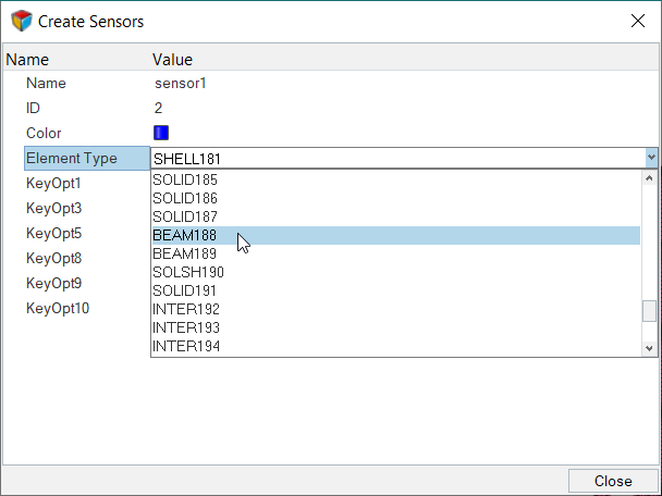
Figure 6. -
In the Select Material dialog, select
Steel and then click OK.
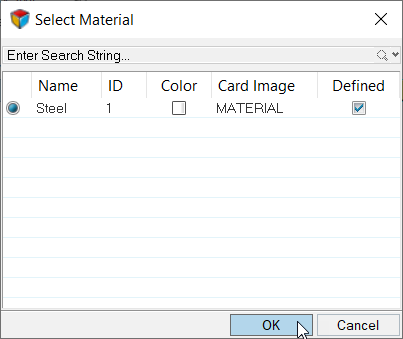
Figure 7. -
For Type, click .
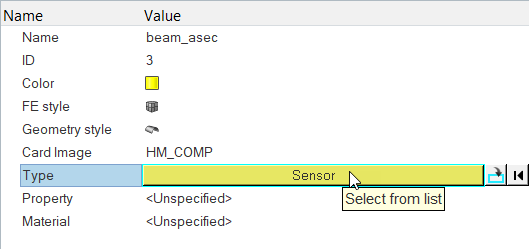
Figure 8. -
In the Select Sensor dialog, select
sensor1 (BEAM188) and then click OK.
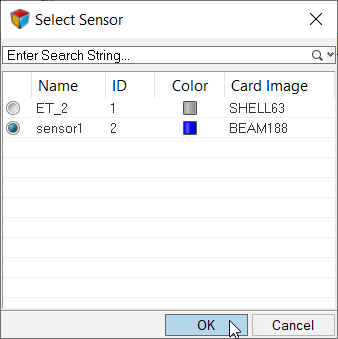
Figure 9.
Create a Beam Element
In this step, you will create a Beam element in HyperMesh.
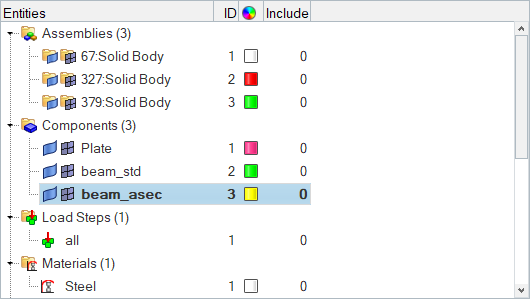
Figure 10.
-
Edit settings within the bar2 subpanel.
-
Set Beam Y Axis to parallel to XY.
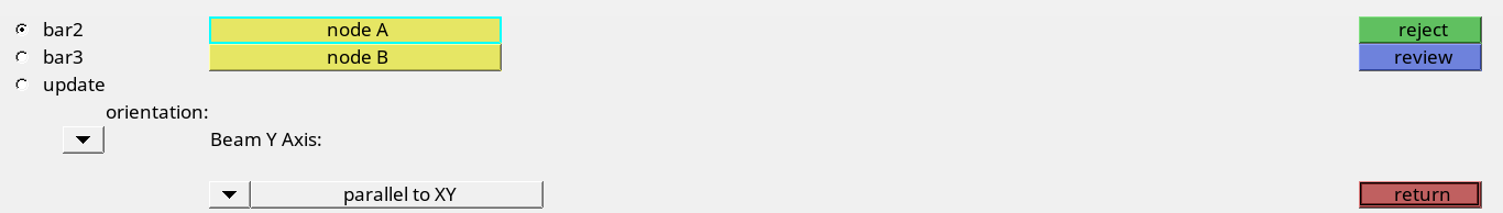
Figure 11.
-
Set Beam Y Axis to parallel to XY.
-
Use the node A and node B selectors to select the two nodes that form the ends
of the Arbitary_Beam_Section line as indicated in Figure 12.
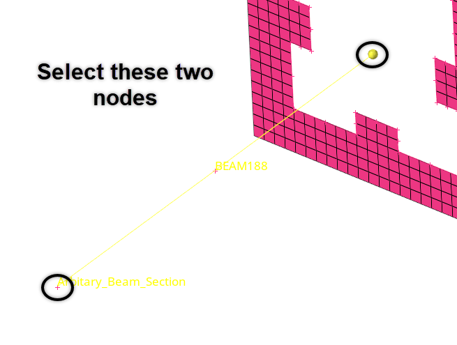
Figure 12.Note: Arbitary_Beam_Section is shown as a tag in the graphics area.HyperMesh creates a BEAM188 element. -
Use the node A and node B selectors to select the two nodes that form the ends
of the Std_circular_Beam_sec line as indicated in Figure 13.
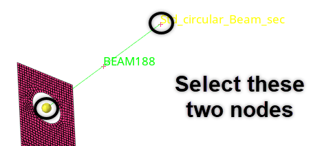 Figure 13. HyperMesh creates a BEAM188 element.
Create Coupled DOF - Rigid Elements
In this step, you will create coupled DOF and rigid elements.
-
Select each of the dof checkboxes as indicated in Figure 14.
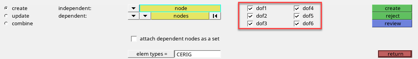
Figure 14. -
On Arbitary_Beam_Section, select the independent node at the end of the beam
element as indicated in Figure 15.
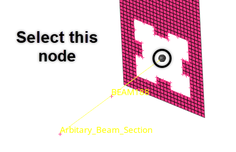
Figure 15. -
On the plate component, select the dependent nodes indicated in Figure 16.
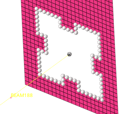
Figure 16. -
Click create.
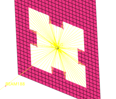
Figure 17. -
On Std_circular_Beam_sec, select the independent node at the end of the beam
element as indicated in Figure 18.
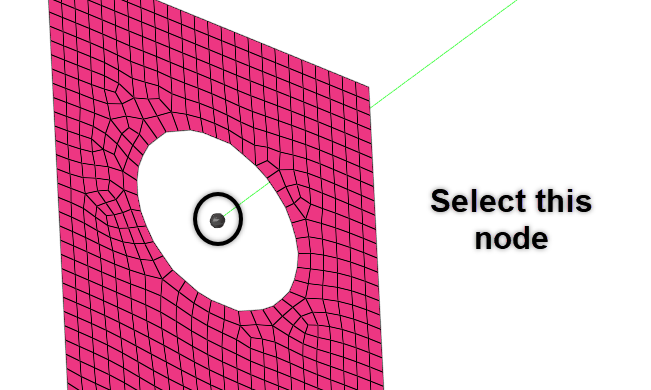
Figure 18. -
On the plate component, select the dependent nodes indicated in Figure 19.
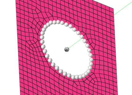
Figure 19. -
Click create.
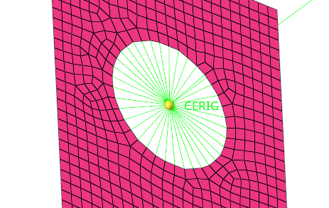
Figure 20.
Create and Attach a Standard Circle Property
In this step, you will create and then attach a standard circle property to a component in HyperMesh.
Create an Arbitrary Property
In this step, you will create an arbitrary property in HyperMesh.
-
In the Component folder of the Model Browser, click
 next to beam_std, beam_asec, and Plate to turn off
the display of their elements.
Note: You should only see geometric entities in the graphics area.
next to beam_std, beam_asec, and Plate to turn off
the display of their elements.
Note: You should only see geometric entities in the graphics area.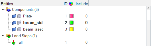
Figure 21. -
Select all of the lines (displayed in pink as indicated in Figure 22) that form the
Arbitrary_Beam_Section.
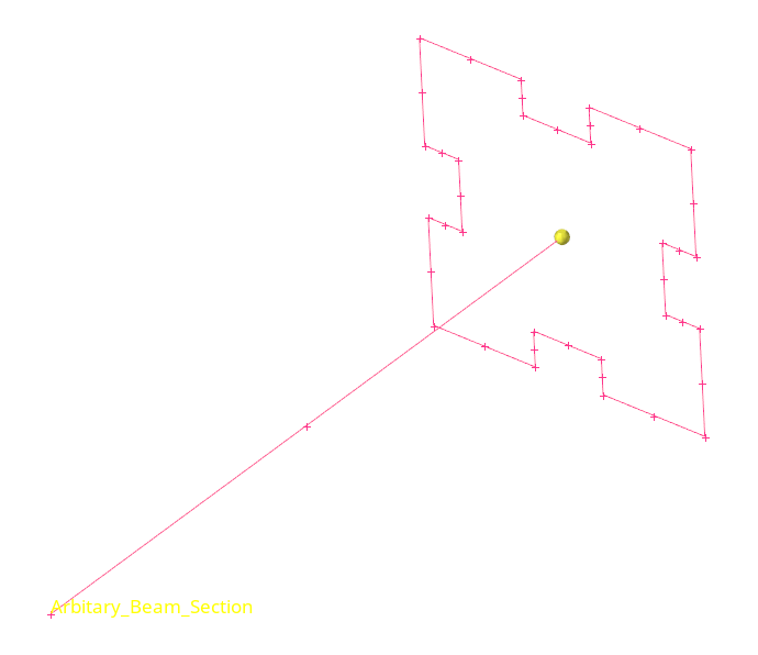
Figure 22. -
Set section base node to centroid.
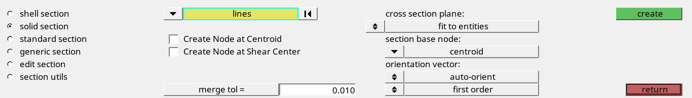
Figure 23. -
Click create.
The HyperBeam Data Model dialog opens, meshes the area enclosed by the selected lines with quadrilateral elements, and calculates the properties using these elements.
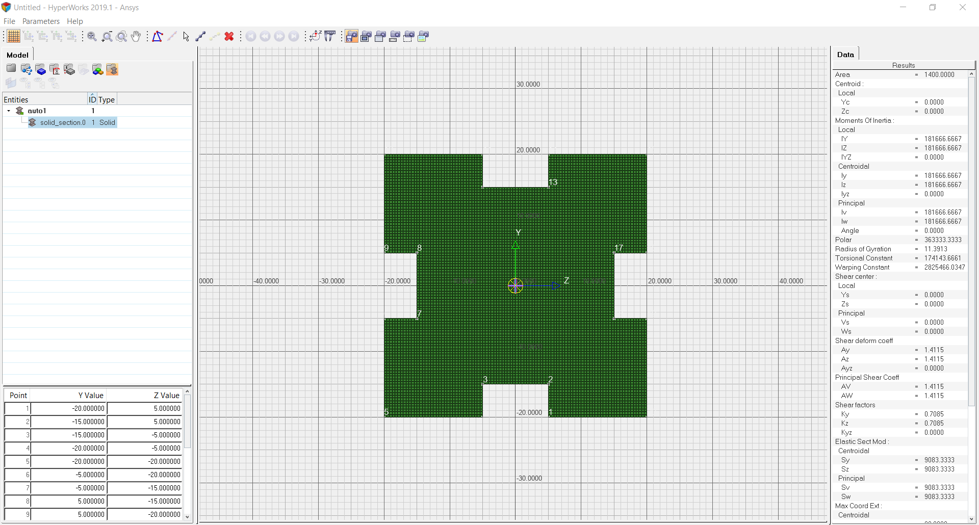
Figure 24. -
In the Model Browser, select
 .
.
-
For Hyper beam section [OPTIONAL], click .
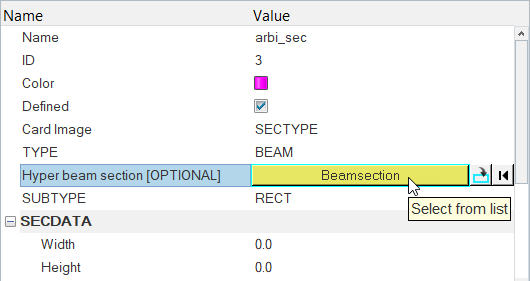
Figure 25.
Update the Component Collector with the Beam Section
In this step, you will update the component collector with the beam section.
-
In the Model Browser, click
 to
display all of the entities in the graphics area.
All of the entities are displayed in the graphics area as indicated in Figure 26.
to
display all of the entities in the graphics area.
All of the entities are displayed in the graphics area as indicated in Figure 26.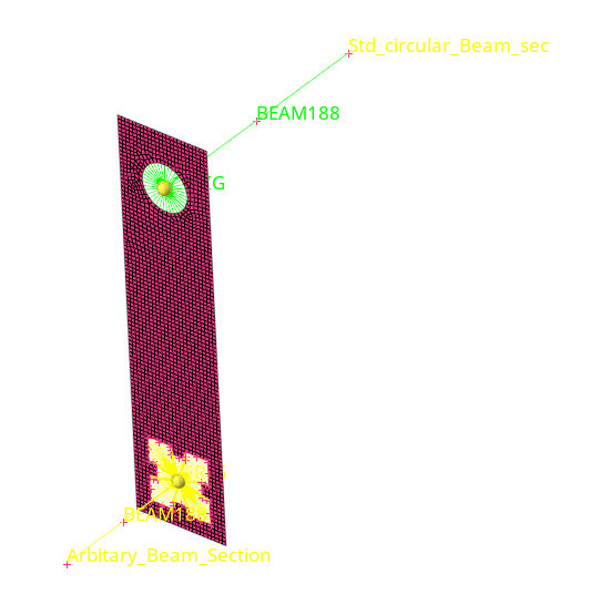
Figure 26.
Save your Work
In this step, you will save your work as a model in HyperMesh.
- From the menu bar, click .
- In the Save Model As dialog, navigate to your working directory and save your file.
Export the Deck to ANSYS *.cdb Format
In this step, you will export your model within HyperMesh.