The nodal time step control is activated for a simulation by using the option:
/DT/NODA/Keyword3/Iflag
With the time step of a node in the mesh defined as:(1)
Where,
Nodal mass
Equivalent nodal stiffness
Note: If the mass of a node increases or the stiffness decreases, then the time
step of the simulation increases.
By default, the nodal timestep is applied to the entire model. If
Iflag=1, then an additional line with a
group node set ID is input after the scale factor and time step. This can be used to
apply the nodal time step control to a group of nodes /GRNOD that
have been defined in the Starter.
Note: No matter which Keyword3
option is used, only one /DT/NODA/Keyword3/Iflag option can
be used at a time in an Engine file. If multiple ones are included, only the
last one is used.
/DT/NODA/CST
/DT/NODA/CST is by far the most popular option for maintaining or
increasing the time step in a simulation. Radioss will
automatically add mass to nodes to maintain the entered value. If needed, the mass
will be added at the beginning of the simulation to meet the entered value.
Advantages and Disadvantages
Increase the nodal mass via
/DT/NODA/CST is the easiest way to increase the time step
of a model or prevent a time step from dropping below a certain value during the
simulation. Good engineering judgement must be used to determine how much mass
is an acceptable amount to be added to a model. Adding too much mass can affect
the physics by increasing the kinetic energy of a drop or impact simulation.
This is because the object being simulated weighs more than the real part.
Increased mass can also change the high frequency behavior of a model which can
be very important in very high speed impacts such as ballistics, or
explosions.
In general, it is recommended to keep the amount of mass added
to less than 5%. However, larger mass increases may be acceptable in some types
of simulation. For example, in quasi-static simulations the velocities are
usually small, so adding mass does not greatly increase the kinetic energy. For
those reasons, it is recommended to check the mass increase in the model by
running a simulation without or with reduced mass scaling and comparing the
results. If added mass results in added kinetic energy, the energy error
calculated by Radioss will be
positive.
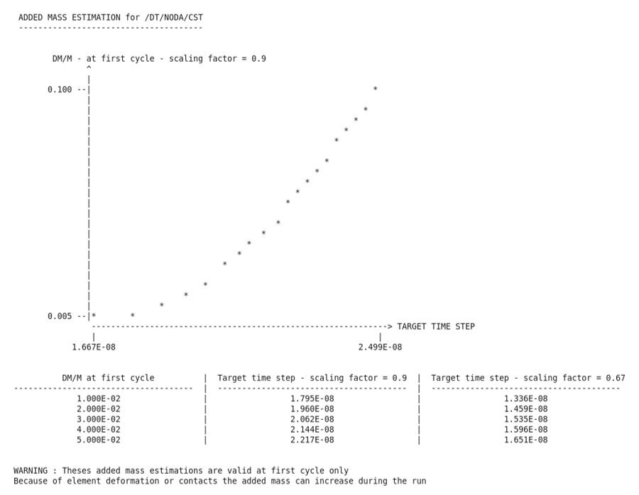
Choose a Time Step for Mass Scaling
To determine how much mass will be
added to a model, Radioss calculates a target time
step for different amounts of percent mass increase. The target time step is
calculated for percent mass increases from 0.5% to 10% for time step scale
factors () of 0.9 and 0.67. This information is printed in a
table and a graph in the Starter output file.
Note: This estimation is valid at
first cycle only. The added mass can increase during the run because of
element deformation or contacts which means the added mass can become higher
than the value expected from the Starter estimation.
Figure 1. Mass Added for Different Target Time Steps
The target time step and scale factor can then used in
/DT/NODA/CST.
Check for Mass Increase
The total mass increase is listed in the Engine
output file in the last column titled, MAS.ERR. Using the
animation output option /ANIM/NODA/DMASS or
/H3D/NODA/DMASS, the relative mass increase per node can
be visualized in a post-processor as a contour plot. Both the total mass error
and nodal mass error represent the change in mass divided by the original mass
at the beginning of the simulation.(2)
With,
Where,
Initial mass at the beginning of the simulation for each Engine
file
Current mass
Note: The initial mass is reset at the beginning of every Engine file
simulation and the total mass increase should be added from all the Engine
output files.
The global time history mass and energy curves
can be plotted to understand how the increased mass effects the simulation.
Note: That part mass output using /TH/PART does not
include the mass added, due to mass scaling.
/DT/NODA/SET
Reduces the equivalent nodal stiffness () to maintain the entered
value. This reduction in stiffness also changes the physics of a simulation and
is typically only used when modeling fluids.
/DT/NODA/STOP
Stops the simulation when the simulation’s time step drops below the entered
value. Many times, a reduction in time step is caused by a model's instability,
so stopping the simulation can be useful to diagnose the issue.