HVVH-4000: CAD Tab
- Compare CAD geometry (CAD IO).
- Compare CAD geometry across different HyperMesh versions (Compare Versions).
- Compare original CAD geometry and an FE mesh after meshing in HyperMesh (CAD > Mesh).
- Compare Meshed FE geometry across different HyperMesh versions (FE-FE).
Compare CAD Geometry
Compare CAD geometry in the CAD IO tab.
-
Under the Input file section, click the file folder icon,
 ,
to load additional input files.
,
to load additional input files.
-
Click the Add File icon,
 , to load raw_iges_data.iges,
located in ..\tutorials\hvvh\CAD\CADIO.
, to load raw_iges_data.iges,
located in ..\tutorials\hvvh\CAD\CADIO.
-
In the Output directory field, click
 to
select an output directory.
to
select an output directory.
-
Click Import/Export.
A report is generated based on the model re-import and comparison with the original CAD geometry, a CAD-CAD comparison. Model file import and export times, as well as import and export status, are displayed.
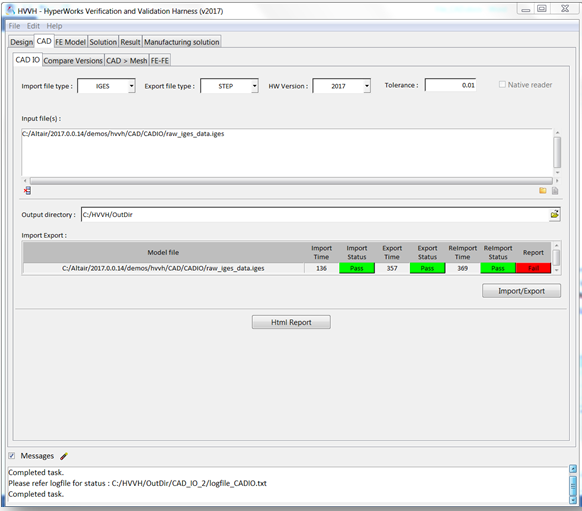
Figure 1.In the Messages window, the run details and log file location are displayed.
If a difference is greater than the tolerance, it is indicated as Fail. Otherwise, they are shown to Pass.
-
Click HTML Report to generate a detailed CAD IO report,
similar to the following examples:
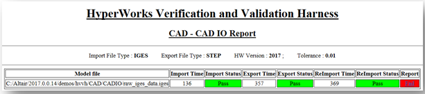
Figure 2.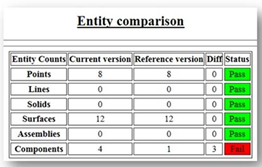
Figure 3.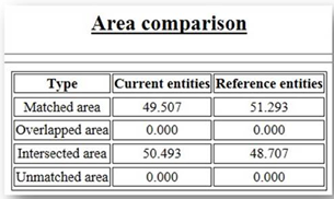
Figure 4.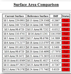
Figure 5.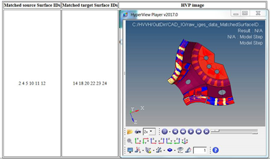
Figure 6.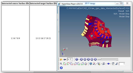
Figure 7.
Compare Versions
Compare CAD geometry across different HyperMesh versions in the Compare Versions tab.
-
From the CAD tab, click the Compare Versions tab.
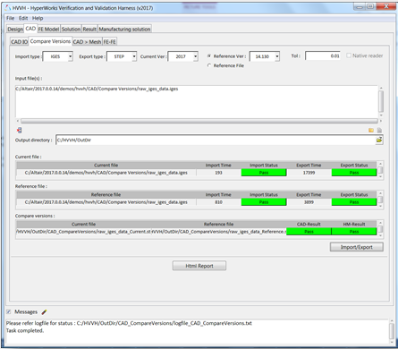
Figure 8. -
Under the Input file section, click the file folder icon, ,
to load additional input files.
-
Click the add file icon, , to load raw_iges_data.iges,
located in ..\tutorials\hvvh\CAD\CompareVersions.
-
In the Output directory field, click the file browser icon, , to
select an output directory.
-
Click HTML Report to generate a detailed report, similar
to the following example:
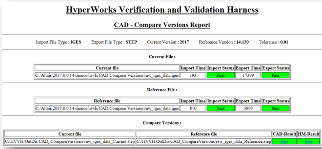
Figure 9.
Compare Original CAD Geometry and an FE Mesh
From the CAD > Mesh tab, compare the original CAD geometry and an FE mesh after meshing in HyperMesh.
-
From the CAD tab, click the CAD > Mesh tab.
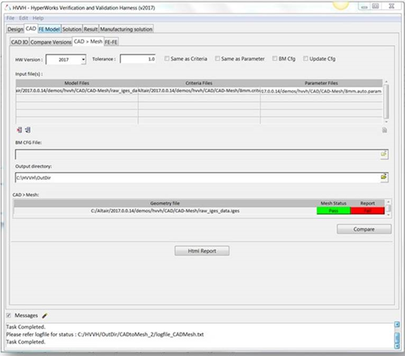
Figure 10. -
Under the Input file section, click the Add File icon,
 , to load additional input files.
-
Click to load the criteria file,
8mm.criteria, located in
..\tutorials\hvvh\CAD\CAD-Mesh.
-
Click to load the parameter file,
8mm.auto.param, located in
..\tutorials\hvvh\CAD\CAD-Mesh.
-
In the Output directory field, click the file browser icon, , to
select an output directory.
-
Click HTML Report to generate a detailed report, similar
to the following examples:
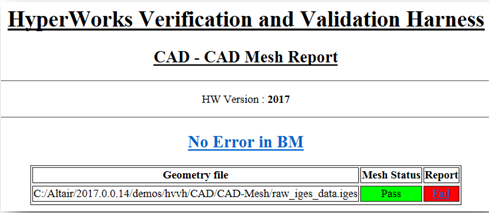
Figure 11.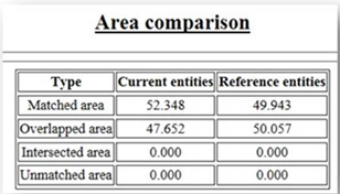
Figure 12.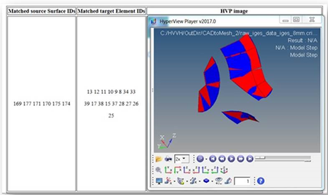
Figure 13.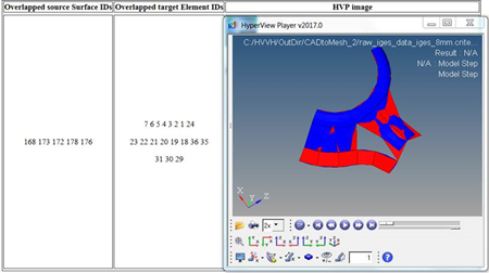 Figure 14.
Compare Meshed FE Geometry Across Different HyperMesh Versions
Compare meshed FE geometry across different versions of HyperMesh using the FE > FE tab.
-
From the CAD tab, click the FE > FE tab.
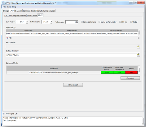
Figure 15. -
Under the Input file section, click the add file icon, , to load the following additional input
files.
- raw_iges_data.iges, located in ..\tutorials\hvvh\CAD\FE-FE
- 8mm.criteria criteria file, located in ..\tutorials\hvvh\CAD\FE-FE
- 8mm.auto.param parameter file, located in ..\tutorials\hvvh\CAD\FE-FE
-
In the Output directory field, click the file browser icon, , to
select an output directory.
-
Click HTML Report to generate a detailed report, similar
to the following examples:
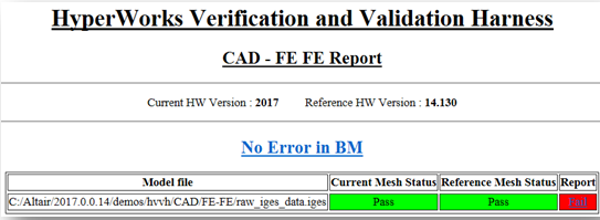
Figure 16.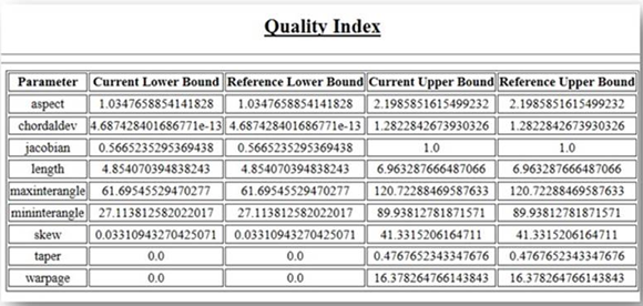
Figure 17.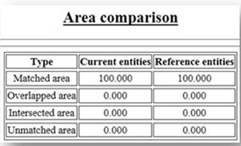
Figure 18.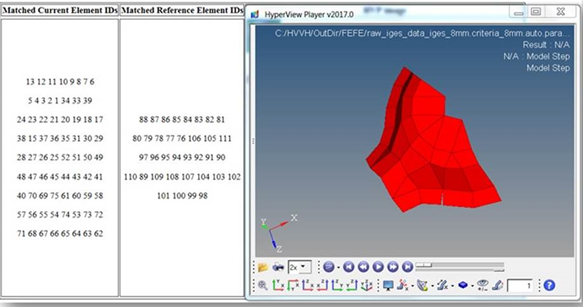
Figure 19.