Turbulent Natural Convection Inside a Tall Cavity
In this application, AcuSolve is used to simulate the natural convection of a turbulent flow field within a tall rectangular cavity. AcuSolve results are compared with experimental results as described in Betts and Bokhari (2000). The close agreement of AcuSolve results with experimental results validates the ability of AcuSolve to model cases with natural convection of turbulent flow within a tall cavity.
Problem Description
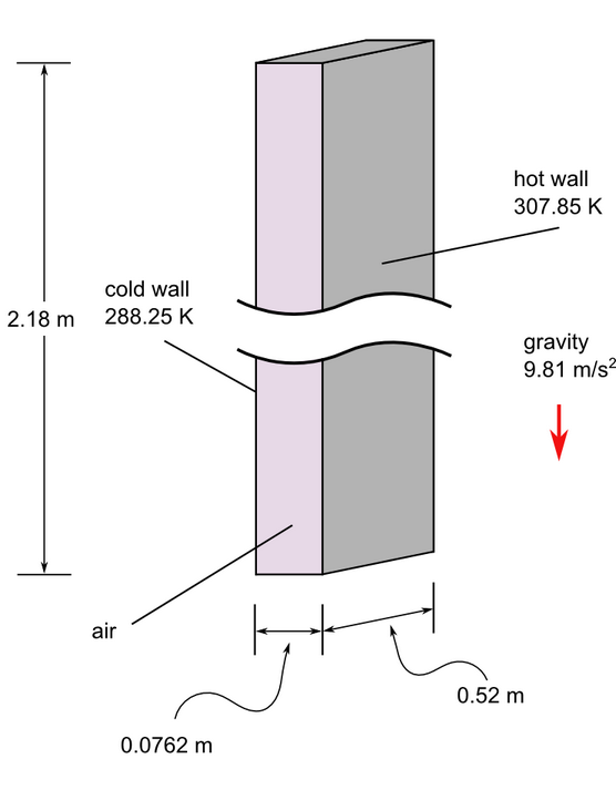
Figure 1. Critical Dimensions and Parameters for Simulating Turbulent Natural Convection in a Tall Cavity
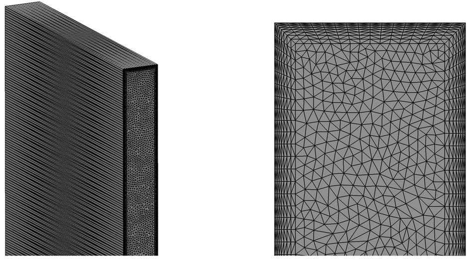
Figure 2. Mesh used for Simulating the Natural Convection of Turbulent Flow in a Tall Cavity
AcuSolve Results
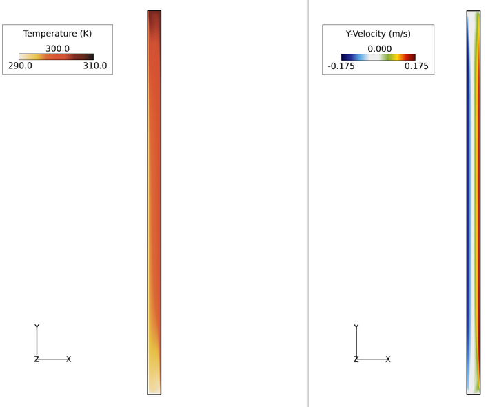
Figure 3. Temperature and Velocity Contours Throughout Tall Cavity in the X-Y Plane
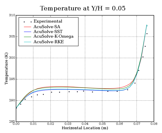
Figure 4. Temperature Plotted against Location along Horizontal at a Position of y/H=0.05 in the Cavity, where H is the Cavity Height and y is the Distance from the Bottom Wall
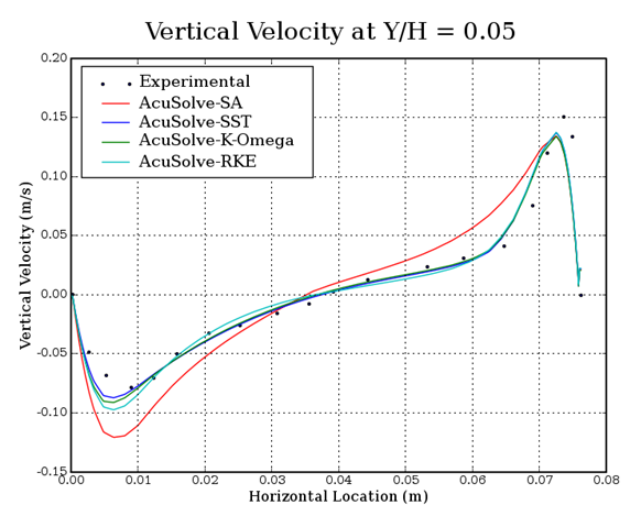 Figure 5. Vertical Velocity Plotted against Location along Horizontal at a Position
of y/H=0.05 in the Cavity, where H is the Cavity Height and y is the
Distance from the Bottom Wall
Figure 5. Vertical Velocity Plotted against Location along Horizontal at a Position
of y/H=0.05 in the Cavity, where H is the Cavity Height and y is the
Distance from the Bottom WallSummary
In this application, turbulent flow developed by natural convection, at a Rayleigh number of 8.6X10⁵, is studied within a tall cavity. The AcuSolve results compare well with the experimental data for temperature and vertical velocity along a horizontal line at a location of y/H=0.05 in the tall cavity, with the two-equation models capturing the velocity gradient with greater accuracy. A temperature difference occurs within the flow region due to the heat transfer from the vertical walls of the cavity. The hotter, less-dense air rises to the top of the cavity while the colder, denser air sinks to the bottom, giving rise to recirculation. AcuSolve demonstrates the ability to accurately predict the natural convection of turbulent flow within a tall cavity.
Simulation Settings for Turbulent Natural Convection Inside a Tall Cavity
AcuConsole database file: <your working directory\cavity_turbulent_heat\cavity_turbulent_heat.acs
Global
- Problem Description
- Analysis type - Steady State
- Turbulence equation - Spalart Allmaras
- Auto Solution Strategy
- Relaxation factor - 0.2
- Material Model
- Air
- Type - Boussinesq
- Density - 1.225 kg/m3
- Specific Heat - 1005 J/kg-K
- Viscosity - 1.781e-5 kg/m-sec
Model
- Air
- Volumes
- Volume
- Element Set
- Material model - Air
- Element Set
- Volume
- Surfaces
- Back
- Simple Boundary Condition
- Type - Symmetry
- Simple Boundary Condition
- Bottom
- Simple Boundary Condition
- Type - Wall
- Temperature BC type - Flux
- Heat Flux - 0.0 W/m2
- Simple Boundary Condition
- Cold
- Simple Boundary Condition
- Type - Wall
- Temperature BC type - Value
- Temperature - 288.25 K
- Simple Boundary Condition
- Front
- Simple Boundary Condition
- Type - Symmetry
- Simple Boundary Condition
- Hot
- Simple Boundary Condition
- Type - Wall
- Temperature BC type - Value
- Temperature - 307.85 K
- Simple Boundary Condition
- Top
- Simple Boundary Condition
- Type - Wall
- Temperature BC type - Flux
- Heat Flux - 0.0 W/m2
- Simple Boundary Condition
- Back
References
P.L. Betts and I.H. Bokhari. "Experiments on Turbulent Natural Convection in an Enclosed Tall Cavity". International Journal of Heat and Fluid Flow 21:675-683. 2000.