Multiphase Flow Within a Sloshing Tank
In this application, AcuSolve is used to simulate water and the time-dependent interface of air-water within a tank subject to a prescribed sloshing motion. AcuSolve results are compared with experimental pressure measurements as reported by Tankaka, et al. (2000) and Rhee (2005). The close agreement of AcuSolve results with experimental results validates the ability of AcuSolve to model multiphase flow problems with user-defined motion.
Problem Description
Where A = amplitude of oscillation, = frequency of oscillation = 2 π/T, t = time (sec) and T = Time period of oscillation (sec).

Figure 1. Critical Dimensions and Parameters for Simulating a 2D Tank Slosh with Mesh Motion
| Cases | Mesh Motion | Amplitude (A) | Time Periods (T) | Tank Filling Level |
|---|---|---|---|---|
| Sway – Base | Sway motion | 0.06 m | 1.94 sec | 20% height |
| Sway – Short | Sway motion | 0.06 m | 1.74 sec | 20% height |
| Roll – Base | Rolling motion | 10 degrees | 2.25 sec | 20% height |
| Roll – Short | Rolling motion | 10 degrees | 1.85 sec | 20% height |
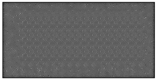
Figure 2. Mesh Used for Simulating Multiphase Sloshing Within a 2D Tank
AcuSolve Results
The AcuSolve solution is run for a time of t/T=5.0, 9.25 sec for Roll - Short, and the results presented reflect the transient motion of the water within the tank. The experimental values of pressure (kPa) and normalized simulation time are presented with the corresponding AcuSolve results at three measurement locations. The AcuSolve results show good agreement with the experimental results for pressure magnitude, the local water column height, as well as accurate timing of the peaks, indicating that the air-water interface is properly captured. Additional motion cases, as well as comparisons between two dimensional versus three dimensional simulations have been simulated with AcuSolve. The accuracy and solution requirements of these simulations are omitted for brevity but are available upon request. It was found that the differences between 2D and 3D simulations may be of interest for engineers, however the 2D results are shown to be adequate and less computationally expensive than 3D in the cases studied.
User-Defined Multiplier Function
This validation case relies on defining the motion of the elements within the tank, leading to the water sloshing in the presence of air. The motion is defined using an AcuSolve User-Defined Function (UDF) to specify the time-dependent multiplier function applied to the mesh motion command. The mesh motion is assigned to the Fluid element set, causing all of the elements to move according to the specified sine function. For the Roll - Short case, the mesh motion command is specified as rotation with the rotation multiplier function specified as rotation. If you are interested in simulating one of the other motion profiles, for example Sway - Base/Short, the type of mesh motion command would be changed to translation with the translation multiplier function assigned with the same UDF. The function name is designated at usrMotion and is contained within the source file motion.c. The source file, along with pre-compiled binaries for Linux64 and Windows64 are provided with the validation case. Depending on your architecture it may be necessary to re-compile the source on the local system. Please refer to the Programs Reference Manual for details on using AcuMakeLib or AcuMakeDll for Linux and Windows, respectively.
Summary
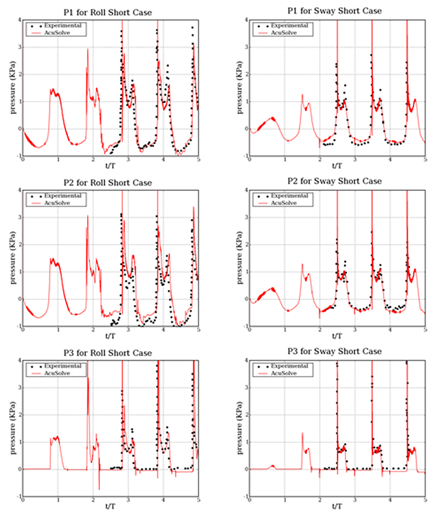
Figure 3. Time Dependent Pressure at Three Monitoring Locations Within the Sloshing Tank for Two Motion Profiles (Roll-Short, Left and Sway-Short, Right)
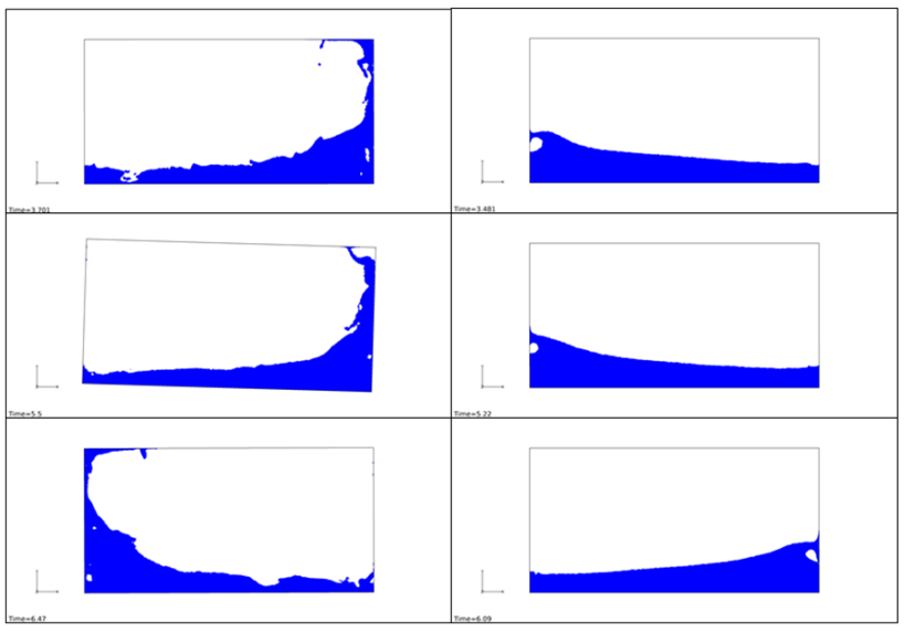
Figure 4. Instantaneous Volume Fraction Contour (Blue Showing Water) at Three Moments in Time (t/T=2.0, 3.0 and 3.5) for Two Motion Profiles (Roll-Short, Left and Sway-Short, Right)
Simulation Settings for Multiphase Flow Within a Sloshing Tank
AcuConsole database file: <your working directory>\tank_sloshing_multiphase\tank_sloshing.acs
Global
- Problem Description
- Analysis type - Transient
- Turbulence equation - SST
- Multiphase equation – Level Set
- Auto Solution Strategy
- Final time - 9.5 sec
- Initial time increment - 0.001 sec
- Min stagger iterations - 2
- Max stagger iterations - 10
- Fluid 1 - Water
- Fluid 2 - Air
- Multiplier Function
- rotation
- Type - User Function
- User function name - UsrMotion
- User function values - 10.0, 1.85, 0.0
- rotation
- Material Model
- Air
- Type - Constant
- Density - 1.225 kg/m3
- Velocity - 1.781e-5 kg/m-sec
- Water
- Type - Constant
- Density - 1000 kg/m3
- Velocity - 0.001 kg/m-sec
- Air
- Mesh motion
- rotation
- Type - Rotation
- Rotation center – 0.0, 0.0, 0.0
- Angular velocity – 0.0, 0.0, 0.0174533 (1.0 deg/sec)
- Rotation variable – Multiplier Function
- Rotation multiplier function – rotation
Model- Volumes
- Fluid
- Element Set
-
Medium – Multiphase
- Multi field model – Water-Air
- Body force – Gravity
- Mesh motion – rotation
-
- Element Set
- Fluid
- rotation
- Surfaces
- x+
- Simple Boundary Condition – Wall
- x-
- Simple Boundary Condition – Wall
- y+
- Simple Boundary Condition – Wall
- y-
- Simple Boundary Condition – Wall
- z+
- Simple Boundary Condition – Slip
- z-
- Simple Boundary Condition – Slip
- x+
References
Shin Hyung Rhee, 2005, “Unstructured Grid Based Reynolds-Averaged Navier-Stokes Method for Liquid Tank Sloshing”, Journal of Fluids Engineering, Vol 127, pp. 572- 582.
Tanaka, Y., Ando, T., and Miyamoto, T., 2000, “Experimental Study on Sloshing Load Measured by Panel-Type Pressure Gauge,” Proc. 74th. General Meeting of Ship Research Institute, Ship Research Institute, Tokyo, Japan, pp. 137-142.