AcuSolve Surface Processing
Auto_Wall
AcuSolve introduces a new feature that greatly simplifies your interaction with the set-up of CFD models that often contain many complex internal and external surfaces. In the classical approach conditions on each surface in the model, or groups of surfaces, must specifically be defined and applied, including standard wall conditions. With the new approach, all surfaces except for inflow, outflow, symmetry, slip and far-field are processed automatically by AcuPrep when type = auto_wall is specified on model surfaces. AcuPrep processes the AUTO_WALL command by first identifying whether a surface is internal or external and then interrogating the model for parent volumes and attributes. Once this information is obtained, the surface sets are sorted and prepared for the supported scenarios. Boundary conditions are applied appropriately when necessary and are not applied when not needed. Output sets for post-processing are created in all cases. When auto_wall is used, reference frame settings applied on volumes will be inherited by the appropriate surfaces. When interfaces are located within the CFD domain for mesh motion applications, auto_wall will automatically split interface surfaces, create the interface surface mechanism with gap or gap factor, and appropriately assign boundary conditions.
Auto_Wall Use Cases
- Solid-Solid, Same Motion
- When two solids of different material are in contact with each other the
interfacing surfaces will be written to a separate output set. No
boundary condition is written in this case, but the surface group is
written for post-processing. In the image below the interface surfaces
between a CPU chip and the PCB are written to two separate output sets.
Sample naming for the pair of output sets is shown below.
- AUTO CPU wall
- AUTO PCB wall
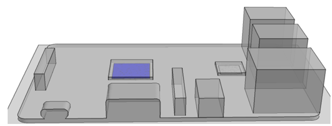
Figure 1. CPU/PCB Interfaces Shown in Blue
- Solid-Solid, Different Motion
- When two solids are in contact with each other and different motion
conditions are applied to each volume the interfacing surfaces will be
written out to separate output sets. No boundary condition is written in
this case, but the surface group is written for post-processing. In
situations where mesh motion is specified internal surfaces will be
split whereas when a reference frame is used no splitting will take
place. In the image below the interface surfaces between a wheel rim and
tire are written to separate output sets. Sample naming for the pair of
output sets is shown below.
- AUTO Rim wall
- AUTO Tire wall
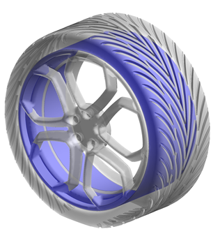
Figure 2. Rim/Tire Interface Shown in Blue
- Fluid-Solid, Same Motion
- When fluid and solid media are in contact with each other and the same motion (or no motion) conditions are applied to each volume the interfacing surfaces will be written out to separate output sets. In the image below the interface surfaces between the cabin air and the seats are written to separate output sets. Sample naming for the pair of output sets is shown below.
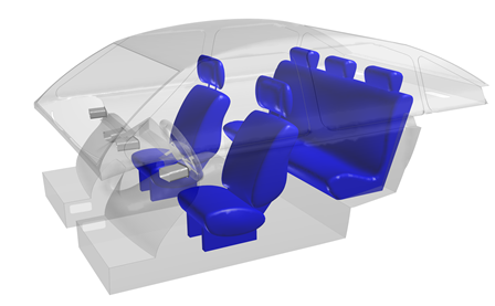
Figure 3. Car Cabin Seats/Air Interface Shown in Blue
- Fluid-Solid, Different Motion
- When fluid and solid media are in contact with each other and different motion conditions are applied to each volume, the interfacing surfaces will be written out to separate output sets and the motion applied to the volumes will be inherited by the appropriate surfaces. In cases where mesh motion is specified internal surfaces will be split whereas in cases where a reference frame is used no splitting will take place. In the image below the interface surfaces of the fan are written to separate output sets. Sample naming for the pair of output sets is shown below.
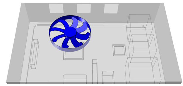
Figure 4. Fan/Air Interface Shown in Blue
- Fluid-Fluid, Same Motion
- When two fluid media are in contact with each other and the same motion conditions are applied to each volume the interfacing surfaces will be written out to separate output sets and the motion applied to the volumes will be inherited by the appropriate surfaces. In the image below the interface surfaces between the upstream and downstream volumes of a pipe flow simulation are written to separate output sets. Sample naming for the pair of output sets is shown below.
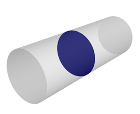
Figure 5. Fluid/Fluid Interface Shown in Blue
- Fluid-Fluid, Different Motion
- When two fluid media are in contact with each other and different motion conditions are applied to each volume the interfacing surfaces will be written out to separate output sets and the motion applied to the volumes will be inherited by the appropriate surfaces. In cases where mesh motion is specified internal surfaces will be split whereas in cases where a reference frame is used no splitting will take place. In the image below the interface surfaces between the rigid body motion zone of the ship hull and the interpolated mesh motion zone are written to separate output sets. Sample naming for the pair of output sets is shown below.
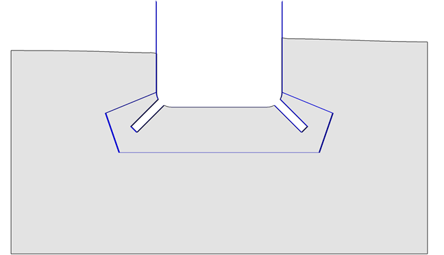
Figure 6. Fluid/Fluid Interface Shown in Blue
- Composite Use of Auto Wall
- All surfaces specified with type =
auto_wall will be processed at the same time. An
example of how a larger collection of surfaces is handled is given
below. In this scenario a pipe geometry, consisting of two cylindrical
volumes, has been imported. The volumes are UpstreamFluid and
DownstreamFluid. You would like to run a simple pipe flow analysis and
specify the same fluid material model on both volumes. You will select
one exterior circular surface to specify as an INLET and the opposite
exterior circular surface as an OUTLET. The remaining surfaces are set
to WALL with type =
auto_wall.
The set of auto_wall surfaces are first examined to determine if they are internal or external and then interrogated for parent volumes and attributes. After processing, surface groups are created with the following naming convention: AUTO <parent_volume_name> <surface_type.
In this example, each of the fluid domain volumes has one external and one internal auto_wall surface. The external surfaces are processed and the result is in one set for each volume. The surface groups are named AUTO UpstreamFluid wall and AUTO DownstreamFluid wall, respectively. Finally, the interfacing surfaces are processed and result in the AUTO UpstreamFluid internal surface group, and a corresponding AUTO DownstreamFluid internal, not shown. No boundary condition is applied to the internal surfaces.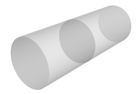
Figure 7. Initial Geometry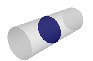
Figure 8. AUTO UpstreamFluid Internal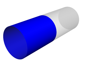
Figure 9. AUTO UpstreamFluid Wall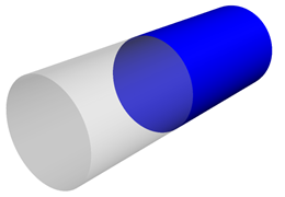
Figure 10. AUTO DownstreamFluid Wall
THERMAL_SHELL
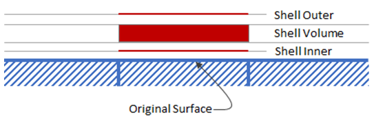
Figure 11.
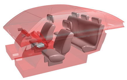
Figure 12. Thermal Shells Created on Car Cabin Surfaces