AcuConsole Mesh Generation Manual
Instruction of the mesh generation capability in AcuConsole, a GUI based pre-processor for AcuSolve.
- Read CAD geometry from Parasolid, ACIS, Granite, ProEngineer and STL formats.
- Generate a mesh on the geometry. Mesh generation in AcuConsole is carried out by a stand-alone executable called AcuMeshSim.
- Read an existing mesh from various formats ( AcuSolve .inp, ICEMCFD, STL, and so on).
- Set analysis attributes and boundary conditions for CFD analysis with AcuSolve.
- Launch AcuSolve
- Monitor the CFD analysis using AcuProbe
- Basic post-processing using AcuOut
- Launch third-party visualization software such as AcuFieldView, EnSight and ParaView.
Mesh generation consists of specifying mesh attributes and launching the mesh generator from AcuConsole. A simple example will be used to demonstrate the mesh generation process in AcuConsole. In this example, a simple pipe model is loaded into AcuConsole. After loading the geometry, one volume group called fluid is created and three surface groups, inflow, outflow and wall, are created.
Once the appropriate geometric faces are attached to the inflow, outflow and wall surface groups, the geometric volume region is attached to the fluid volume group. A geometric face is a two dimensional entity bounded by edges. Each Surface group can have one or more geometric faces. A geometric region is a three dimensional entity bounded by geometric faces. Each Volume group can have one more geometric regions.
Once this is complete, the Launch AcuMeshSim dialog is opened by clicking .
The Launch AcuMeshSim dialog has some basic and advanced parameters that control the meshing process. Keep all the default values, then click OK.
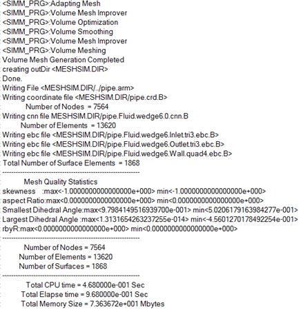
Figure 1.
Once the mesh generation is complete, the mesh data is written on the disk and AcuConsole notifies you that the mesh generation was successful.
Boundary conditions and other simulation attributes can be set with or without mesh or geometry loaded in AcuConsole. Once the simulation attributes are set, AcuSolve can be launched to perform the CFD analysis.
There are many levels of mesh controls that are provided in AcuConsole to get the desired element sizing. Mesh controls can be set at the model level, at the individual volume level, or at the surface level. In addition, AcuConsole has the capability to set the mesh sizes as a function of space through Zone Mesh Attributes. All of the mesh attributes are hierarchical in AcuConsole. That is, a mesh size applied to the entire model will be inherited by each of the geometric faces and regions in the model. A mesh size applied to a volume region will be inherited by all of the faces attached to the volume region. All of the geometric entities that have an overlap with any of the zone mesh attributes will inherit mesh sizes from the zone mesh attributes. AcuConsole uses the smallest of all the sizes that are applied to a geometric entity to determine the final mesh size setting. For example, in the pipe model if a global mesh size of 5mm is set, and a mesh size of 1mm is set on the inflow surface, AcuConsole uses the mesh size of 1mm on the inflow surface and 5mm everywhere else. Similarly, if a mesh size of 1mm is set as global mesh size and a value of 5mm is set on the inflow surface, AcuConsole uses 1mm everywhere, including the inflow surface, since 1mm < 5mm.
In each of the mesh attributes panels, mesh size is the most fundamental quantity that is modified. AcuConsole supports various methods for defining the mesh size.