Edge Mesh Attributes
An edge mesh specifies mesh attributes along a selected edge of a model.
Example of Absolute Mesh Size along an Edge
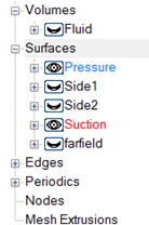
Figure 1.
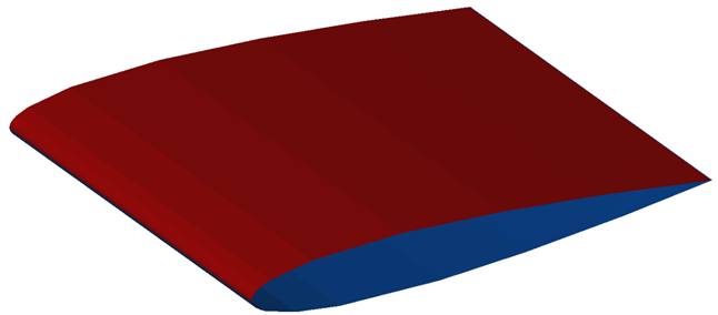
Figure 2.
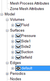
Figure 3.
To identify the edge, right-click on Edges and select New. Create as many new groups as there are edges which will be assigned mesh properties. Rename the edge groups, if desired.
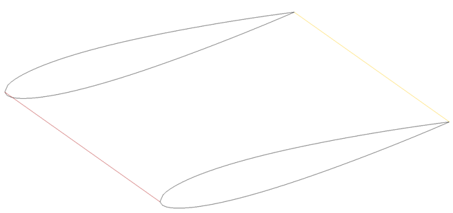
Figure 4.
The absolute mesh size along the leading edge is defined by right-clicking on the edge group, or double clicking on the name. This will bring up a panel where the mesh requirements are specified.
The Edge Mesh Attribute panel is much like the panels for surface and volume mesh size. The mesh size type is defined by either Absolute, Relative, Absolute Expression, Relative Expression, Absolute Anisotropic or Relative Anisotropic. This example uses Absolute as the mesh size type to specify the mesh along the leading edge.
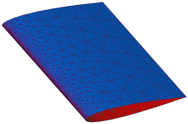
Figure 5.
The other mesh size specifications work the same way the surface mesh size specifications do.