Turbulent Flow with Separation in an Asymmetric Diffuser
In this application, AcuSolve is used to simulate fully developed turbulent flow through an asymmetric diffuser with a divergent lower wall and a straight upper wall. AcuSolve results are compared with experimental results as described in Buice and Eaton (1996). The close agreement of AcuSolve results with experimental results validates the ability of AcuSolve to model cases with internal turbulent flow with flow separation and reattachment in an asymmetric diffuser.
Problem Description
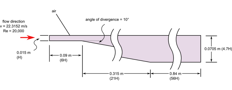
Figure 1. Critical Dimensions and Parameters for Simulating Turbulent Flow with Separation in an Asymmetric Diffuser
Figure 2. Mesh Details Near the Inlet and Divergent Section of Diffuser
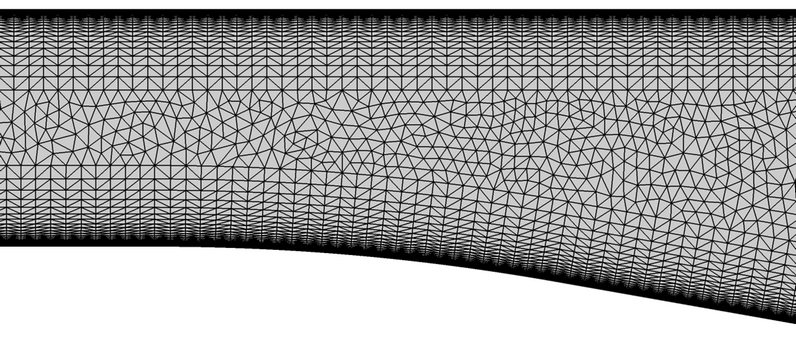
Figure 3. Mesh Details at the Beginning of the Divergence of the Lower Wall in the Diffuser
AcuSolve Results
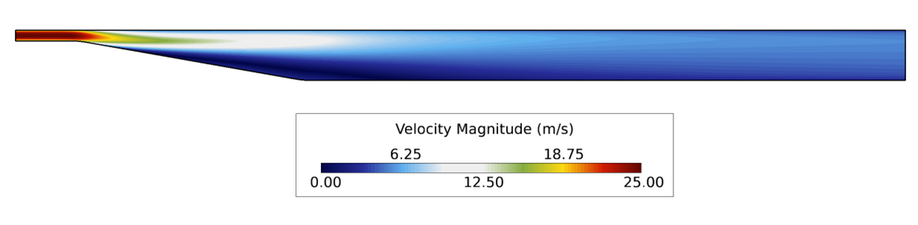
Figure 4. Velocity Contours Within the Diffuser
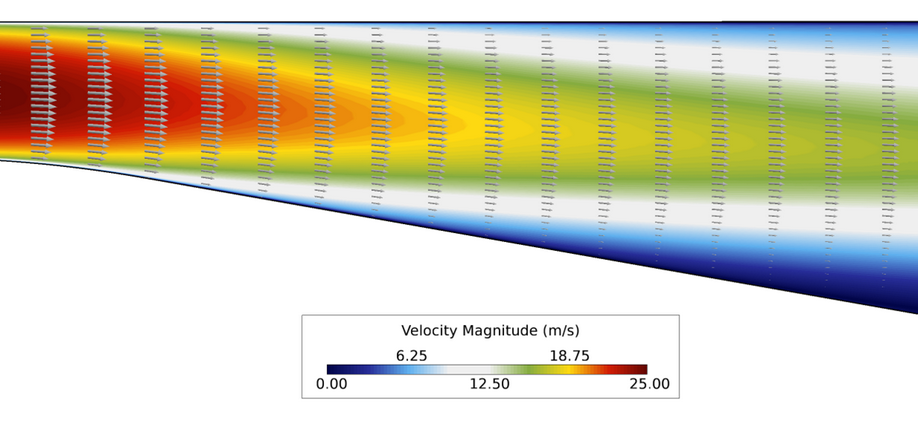
Figure 5. Close up View of Velocity Vectors and Contours of Velocity Magnitude in the Diffuser
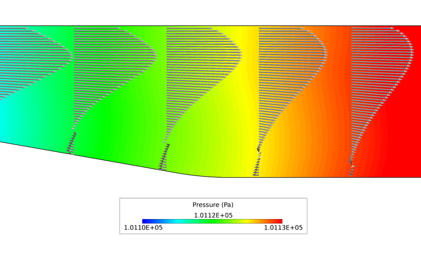
Figure 6. Close up View of Velocity Vectors and Contours of Pressure to Show Recirculation as it Approaches the Reattachment Point
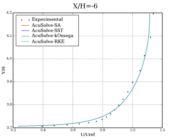
Figure 7. Non-Dimensional Streamwise Velocity Plotted Against Vertical Location Near the Inlet (X/H=-5.9442, Where the Reference Point is 6H Downstream of the Inlet)
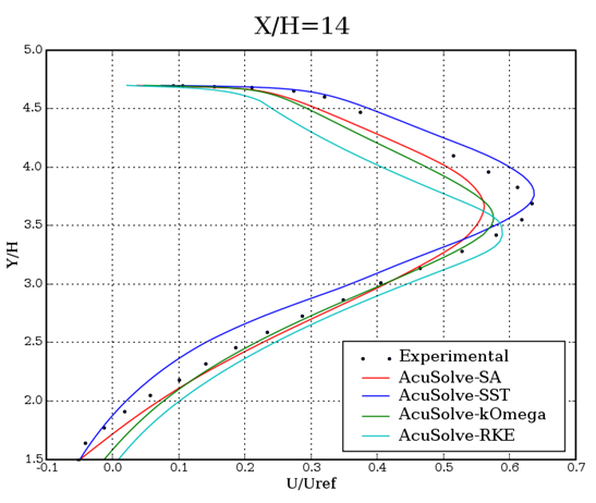
Figure 8. Non-Dimensional Streamwise Velocity Plotted Against Vertical Location Approximately 0.2 m Downstream of the Divergence (X/H = 13.468, Where the Reference Point is 6H Downstream of the Inlet)
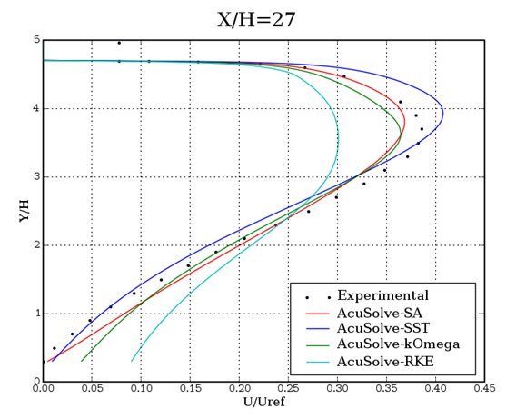
Figure 9. Non-Dimensional Streamwise Velocity Plotted Against Vertical Location Approximately 0.2 m Downstream of the Transition to the Fully Divergent Section (X/H = 27.066, Where the Reference Point is 6H Downstream of the Inlet)
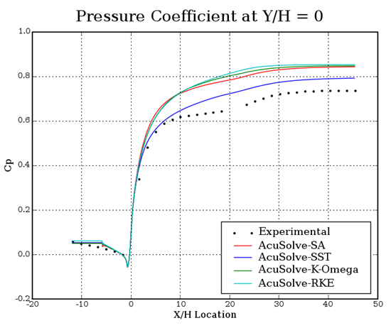
Figure 10. Non-Dimensional Pressure Coefficient (Cp) Plotted Against Relative Distance Along the Diffuser at a Constant Height Equal to the Bottom of the Inlet
Summary
In this application, a fully developed turbulent flow at a Reynolds number of 20,000 is studied. Due to the adverse pressure gradient, separation of flow occurs and causes recirculation in the divergent section of the diffuser. The results were found to be consistent with previously published computational studies and experimental data. The results of this validation demonstrate the ability of AcuSolve to accurately predict the separation point, the recirculation that occurs along the divergent wall, and the reattachment point in the straight section of the diffuser.
Simulation Settings for Turbulent Flow with Separation in an Asymmetric Diffuser
AcuConsole database file: <your working directory>\asymmetric_diffuser_turbulent\asymmetric_diffuser_turbulent.acs
Global
- Problem Description
- Analysis type - Steady State
- Turbulence equation - Spalart Allmaras
- Auto Solution Strategy
- Max time steps - 150
- Relaxation Factor - 0.2
- Material Model
- Air
- Density - 1.225.0 kg/m3
- Viscosity - 1.8325e-5 kg/m-sec
Model
- Air
- Volume
- Volume
- Element Set
- Material model - Air
- Element Set
- Volume
- Surfaces
- Bottom
- Simple Boundary Condition
- Type - Wall
- Simple Boundary Condition
- Inlet
- Simple Boundary Condition (disabled to allow for nodal boundary conditions to be set)
- Advanced Options
- Nodal Boundary Conditions
- X-Velocity
- Type - Linear
- Precedence - 2
- Curve fit variable - Y coordinate
- Curve fit values (included in .acs)
- Y-Velocity
- Type - Linear
- Precedence - 2
- Curve fit variable - Y coordinate
- Curve fit values (included in .acs)
- Eddy Viscosity
- Type - Linear
- Precedence - 2
- Curve fit variable - Y coordinate
- Curve fit values (included in .acs)
- X-Velocity
- Nodal Boundary Conditions
- Outlet
- Simple Boundary Condition
- Type - Outflow
- Simple Boundary Condition
- Side 1
- Simple Boundary Condition
- Type - Symmetry
- Simple Boundary Condition
- Side 2
- Simple Boundary Condition
- Type - Symmetry
- Simple Boundary Condition
- Top
- Simple Boundary Condition
- Type - Wall
- Simple Boundary Condition
- Bottom
References
C.U. Buice, and J.K., Eaton. "Experimental Investigation of Flow Through an Asymmetric Plane Diffuser". Journal of Fluids Engineering 122:433-435. June 2000.
S. Obi, K. Aoki and S. Masuda. "Experimental and Computational Study of Turbulent Separating Flow in an Asymmetric Plane Diffuser". Ninth Symposium on Turbulent Shear Flows. p. 305. Kyoto, Japan. August 16-19, 1993.