Circumferential Flow in a Cylinder Induced by a Rotating Solid
In this application, AcuSolve is used to simulate the flow of air between concentric cylinders that is initiated by the rotation of the solid inner cylinder. The outer cylinder is held stationary while the inner cylinder rotates with a constant speed. AcuSolve results are compared with analytical results as described in White (1991). The close agreement of AcuSolve results with analytical results validates the ability of AcuSolve to maintain a continuous velocity across a non-conformal guide surface interface.
Problem Description
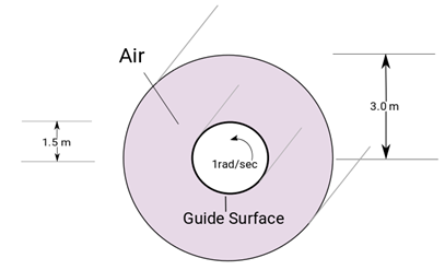
Figure 1. Critical Dimensions and Parameters Used for Simulating Flow Between Two Concentric Cylinders Split with a Guide Surface
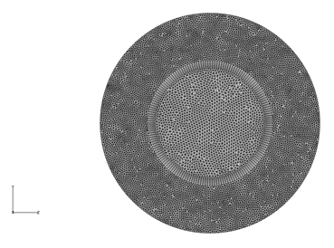
Figure 2. Mesh Used for Simulating Flow Between Two Concentric Cylinders
The simulation was performed as a two dimensional problem by constructing a volume mesh that contains a single layer of elements in the extruded direction, normal to the flow plane and by imposing slip flow and mesh boundary conditions on the extruded planes.
AcuSolve Results
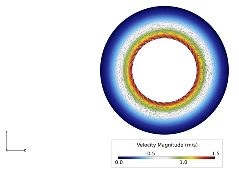
Figure 3. Contours and Vectors of Velocity Between the Concentric Cylinders
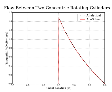
Figure 4. Tangential Velocity Within the Solid and Fluid as a Function of Radial Distance from the Center at the Final Timestep
Summary
The AcuSolve solution compares well with analytical results for laminar flow between concentric cylinders, where the inner cylinder guides the adjacent fluid elements. In this application, a fluid initially at rest inherits the angular velocity from the inner cylinder while the outer cylinder does not rotate. As a result of the inherited velocity and viscosity of the fluid, flow develops between the two cylinders. The AcuSolve solution for the tangential velocity as a function of radius matches exactly with the analytical results.
Simulation Settings for Flow Between Concentric Split Cylinders
AcuConsole database file: <your working directory>\annulus_split_rotating\annulus_split_rotating.acs
- Problem Description
- Analysis type - Transient
- Flow equation - Navier Stokes
- Turbulence equation - Laminar
- Mesh type - Arbitrary Mesh Movement (ALE)
- Auto Solution Strategy
- Max time steps - 40
- Initial time increment- 0.02 sec
- Convergence tolerance - 0.001
- Min stagger iterations - 2
- Max stagger iterations - 4
- Material Model
- Air
- Density
- Type - Constant
- Density - 1.225 kg/m3
- Viscosity
- Type - Constant
- Viscosity - 1.781 kg/m-sec
- Density
- Air
- Mesh Motion
- Rotation
- Rotation Center
- X-coordinate - 2.0 m
- Y-coordinate - 0.0 m
- Z-coordinate - 0.0 m
- Angular velocity
- X-component - 1.0 rad/sec
- Y-component- 0.0 rad/sec
- Z-component - 0.0 rad/sec
- Rotation Center
Model
- Rotation
- Volumes
- CylinderInner
- Element Set
- Medium - Solid
- Material model - Aluminum
- Element Set
- CylinderOuter
- Element Set
- Medium - Fluid
- Material model - Air
- Element Set
- CylinderInner
- Surfaces
- InBottom
- Simple Boundary Condition
- Type- Slip
- Mesh displacement type- Slip
- Simple Boundary Condition
- InInterf
- Simple Boundary Condition
- Type- Wall
- Mesh displacement type- Fixed
- Mesh motion- Rotation
- Guide Surface
- Type- Faceted
- Simple Boundary Condition
- InTop
- Simple Boundary Condition
- Type- Slip
- Mesh displacement type- Slip
- Simple Boundary Condition
- OutBottom
- Simple Boundary Condition
- Type- Slip
- Mesh displacement type- Slip
- Simple Boundary Condition
- OutInterf
- Simple Boundary Condition
- Type- Wall
- Wall velocity type- Match Mesh Velocity
- Mesh displacement type- Guide surface
- Guide surface- InInterf
- Simple Boundary Condition
- OutTop
- Simple Boundary Condition
- Type- Slip
- Mesh displacement type- Slip
- Simple Boundary Condition
- OutWall
- Simple Boundary Condition
- Type- Wall
- Mesh displacement type- Fixed
- Simple Boundary Condition
- InBottom
- Nodes
- PressurePoint
- Pressure
- Type- Zero
- Pressure
- PressurePoint
References
F. M. White. "Viscous Fluid Flow". Section 3-2.3. McGraw-Hill Book Co., Inc. New York. 1991.