Ideal Gas Compression in an Actuating Piston
In this application, AcuSolve is used to simulate pressure and temperature inside an actuating piston using the ideal gas relationship and fully defined mesh motion. AcuSolve results are compared with analytical results as described in Moran and Shapiro (2000). The close agreement of AcuSolve results with analytical results validates the ability of AcuSolve to model cases with material properties defined by the ideal gas law subjected to significant mesh distortion.
Problem Description
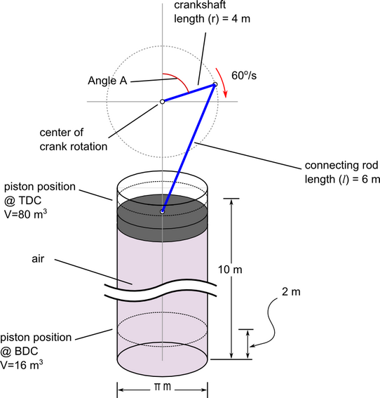
Figure 1. Critical Dimensions and Parameters for Simulating Ideal Gas Compression in an Actuating Piston
The motion of the piston is described by the following equation.
- x is the distance of the piston from TDC
- r is the length of the connecting rod, 4 m
- A is the crank angle as a function of time (t)
- l is the connecting rod length, 6 m
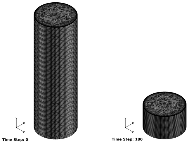
Figure 2. Mesh Used for Simulating Ideal Gas Compression in an Actuating Pistion at Time Step 0 and Time Step 180 (3 s)
AcuSolve Results
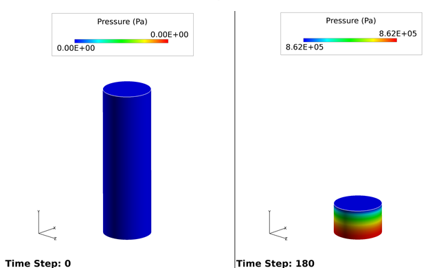
Figure 3. Pressure Distribution Within the Domain with the Piston at TDC and BDC
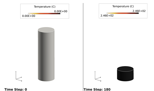
Figure 4. Temperature Distribution Within the Domain with the Piston at TDC and BDC
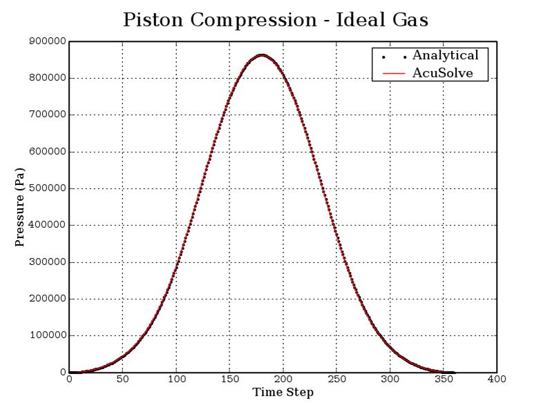
Figure 5. History Plots of Pressure for AcuSolve and Analytical Solutions
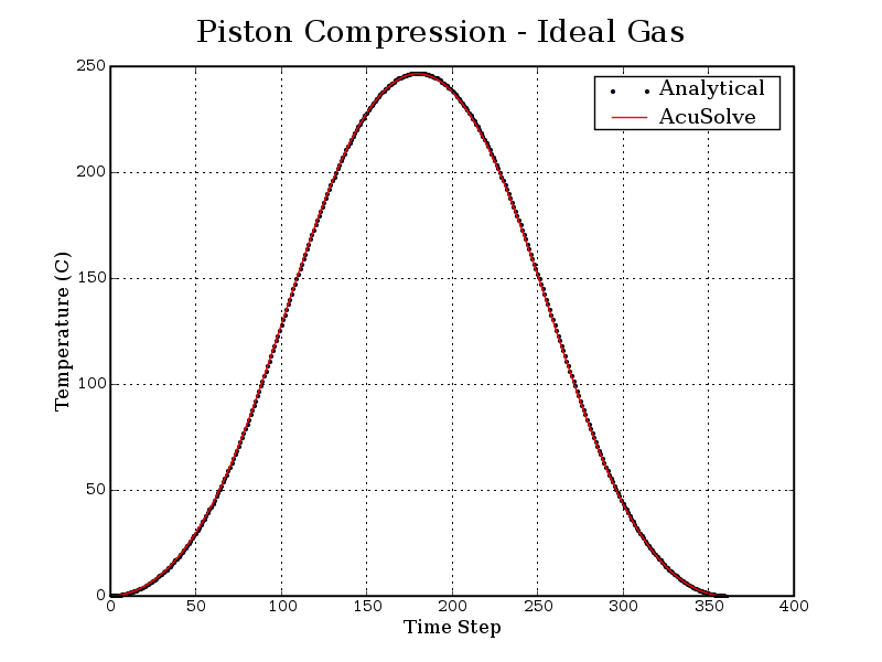
Figure 6. History Plots of Temperature for AcuSolve and Analytical Solutions
Summary
The AcuSolve solution compares well with analytical results for ideal gas compression in an actuating piston. The AcuSolve transient solution compares nearly identically with the analytical solution, with 0.1 percent and 0.16 percent error for the maximum pressure and temperature, respectively. As a result, AcuSolve demonstrates the ability to predict ideal gas compression in an actuating piston.
Simulation Settings for Ideal Gas Compression in an Actuating Piston
AcuConsole database file: <your working directory>\cylinder_piston_compression\cylinder_piston_compression.acs
Global
- Problem Description
- Analysis type - Transient
- Temperature equation - Advective Diffusive
- Turbulence equation - Laminar
- Mesh type - Fully Specified
- Auto Solution Strategy
- Max time steps - 360
- Initial time increment - 0.01667 sec
- Convergence tolerance - 1.0e-5 sec
- Max stagger iterations - 10
- Multiplier Function
- Piston
- Type - Piecewise Linear
- Curve fit variable - Time
- Curve fit values - (included in .acs based on equation discussed in problem description)
- Piston
- Material Model
- Air
- Density
- Type - Ideal Gas
- Gas constant - 286.9 J/kg-K
- Abs. pressure offset - 101325.0 N/m2
- Abs. temperature offset - 273.15 K
- Viscosity - 1.781e-5 kg/m-sec
- Density
- Air
- Mesh Motion
- Piston
- Type - Translation
- Translation velocity - 0.0, -1.0, 0.0
- Velocity variable - Multiplier Function
- Translation multiplier function - Piston
Model
- Piston
- Volumes
- Fluid
- Element Set
- Material model - Air
- Compression heating - On
- Element Output - on
- Element Set
- Fluid
- Surfaces
- BDC
- Simple Boundary Condition
- Type - Wall
- Wall velocity type - Match Mesh Velocity
- Mesh displacement BC type - Fixed
- Simple Boundary Condition
- SideWall
- Simple Boundary Condition
- Type - Wall
- Wall velocity type - Match Mesh Velocity
- Mesh displacement BC type - Fixed
- Simple Boundary Condition
- TDC
- Simple Boundary Condition
- Type - Wall
- Mesh displacement BC type - Fixed
- Mesh motion - Piston
- Simple Boundary Condition
- BDC
- Nodes
- VolumeNodes
- Mesh X-Displacement
- Type - Zero
- Mesh Y-Displacement
- Type - Linear
- Mesh motion - Piston
- Curve fit variable - Y reference coordinate
- X1 - 10.0 m
- Y1 - 1.0 m
- Y2 - 0.0 m
- Mesh Z-Displacement
- Type - Zero
- Mesh X-Displacement
- VolumeNodes
References
M.J. Moran and H.N Shapiro. "Fundamentals of Engineering Thermodynamics". Wiley. 4th Ed. 2000.