Laminar Free Surface Flow Inside a Rotating Cavity
In this application, AcuSolve is used to solve for the flow field within a rotating cavity with the top of the cavity free to move as if it was exposed to air. The height of the free surface is determined and compared against the analytical solution for the same rotational velocity under the standard gravitational force.
Problem Description

Figure 1. Critical Dimensions and Parameters used for Simulating a Laminar Free Surface Inside a Rotating Cavity
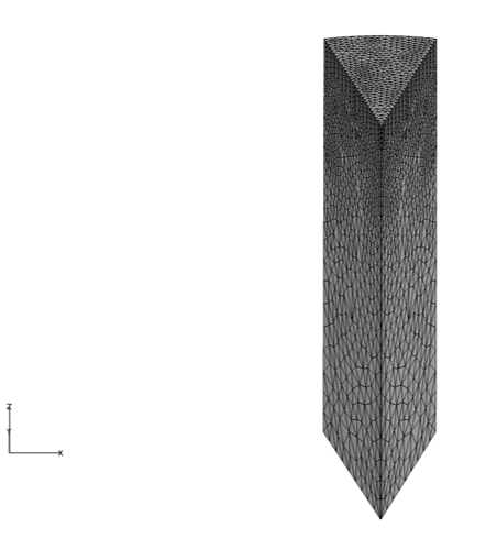
Figure 2. Mesh used for Simulating Laminar Free Surface Flow Inside a Rotating Cavity
The problem is simulated as axisymmetric by considering a 30 degree portion of the cavity with rotationally periodic boundary conditions applied on the planar surfaces representing the cut faces of the cavity.
AcuSolve Results

Figure 3. Free Surface Height of the Fluid Within the Cavity as a Function of Distance from the Center of the Domain at the Final Timestep
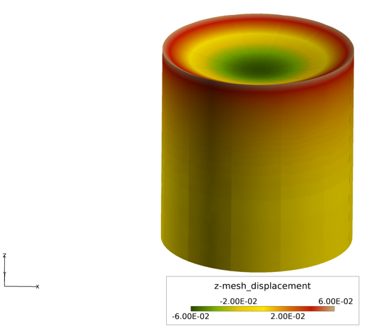
Figure 4. Vertical Mesh Displacement Within the Rotating Cavity at the Final Time Step (Shown as the Complete Cavity, using the Results from the Axisymmetric Section)
Summary
The AcuSolve solution compares well with analytical results for laminar free surface flow inside a rotating cavity. In this application, a fluid initially at rest is subjected to an angular velocity about the center of the cavity. As a result of the prescribed velocity, the fluid is forced to the outer wall of the cavity and develops a free surface profile in the shape of a parabola. The AcuSolve solution for the free surface height matches nearly exactly with the analytical results, with only minor differences based on the convergence criteria that you specified.
Simulation Settings for Laminar Free Surface Flow Inside a Rotating Cavity Fluid
Global
- Problem Description
- Analysis type - Transient
- Flow equation - Navier Stokes
- Turbulence equation - Laminar
- Mesh type - Arbitrary Mesh Movement (ALE)
- Auto Solution Strategy
- Final time - 15.0 sec
- Initial time increment- 0.05 sec
- Convergence tolerance - 0.001
- Min stagger iterations - 0
- Max stagger iterations - 4
- Material Model
- Fluid
- Density
- Type - Constant
- Density - 10 kg/m3
- Viscosity
- Type - Constant
- Viscosity - 3.0 kg/m-sec
- Density
- Fluid
- Reference Frame
- Omega
- Rotation Center
- X-coordinate - 0.0 m
- Y-coordinate - 0.0 m
- Z-coordinate - 0.0 m
- Angular velocity
- X-component - 0.0 rad/sec
- Y-component- 0.0 rad/sec
- Z-component - 3.0 rad/sec
- Rotation Center
Model
- Omega
- Volumes
- Fluid
- Element Set
- Material model - Fluid
- Body force - Gravity
- Reference frame - Omega
- Element Set
- Fluid
- Surfaces
- + Y
- Simple Boundary Condition - (disabled to allow for nodal boundary conditions)
- Advanced Options
- Nodal Boundary Conditions
- X-velocity
- Type - Constant
- Reference frame - Omega
- Constant value - 0.0
- Y-velocity
- Type - Constant
- Reference frame - Omega
- Constant value - 0.0
- Mesh X-Displacement
- Type- Zero
- Mesh Y-Displacement
- Type- Zero
- X-velocity
- Nodal Boundary Conditions
- -Z
- Simple Boundary Condition
- Type - Wall
- Reference frame - Omega
- Mesh displacement BC type - Fixed
- Simple Boundary Condition
- Axisymmetric +X
- Simple Boundary Condition (disabled to allow for nodal boundary conditions)
- Axisymmetric -X
- Simple Boundary Condition (disabled to allow for nodal boundary conditions)
- Free_Surface
- Simple Boundary Condition
- ⃣ Type - Free Surface
- Simple Boundary Condition
- + Y
- Periodics
- Axisymmetric Condition
- Periodic Boundary Condition
- Type - Axisymmetric
- Rotation Axis
- Point 1
- x-coordinate - 0.0 m
- y-coordinate - 0.0m
- z-coordinate - 0.0m
- Point 2
- x-coordinate - 0.0 m
- y-coordinate - 0.0m
- z-coordinate - 1.0m
- Point 1
- Nodes
- All
- Mesh X-Displacement
- Type - Zero
- Mesh Y-Displacement
- Type - Zero
- Mesh X-Displacement
- Centerline
- X-Velocity
- Type - Zero
- Y-velocity
- Type - Zero
- Mesh X-Displacement
- Type - Zero
- Mesh Y-Displacement
- Type - Zero
- X-Velocity
- All
References
White, F. Fluid Mechanics. New York: McGrawHill. 2003