Entity Display
The Entity Attributes panel allows you to change the display attributes of model entities.
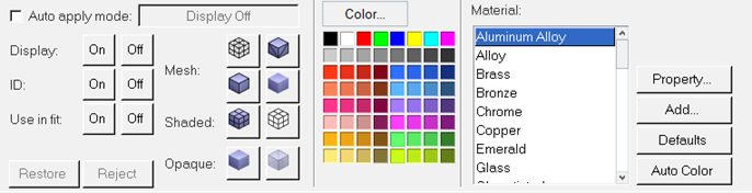
Figure 1.
- Mesh
- There are four line options to apply to FEA model components:
- Mesh Lines

- Feature Lines

- Edge Lines

- No lines

Click the appropriate button to display the desired feature; click another button to remove the feature.
- Mesh Lines
- Shaded
- Entities can be displayed as a shaded or wire frame drawing.
- Click
 to display the selected entities as a
shaded drawing.
to display the selected entities as a
shaded drawing. - Click
 to display the selected entities as a
wire frame drawing.
to display the selected entities as a
wire frame drawing.
- Click
- Opaque
- Entities can be either opaque or transparent. Opaque entities are solid and hide the
entities behind them. Transparent entities are see-through and reveal the obscured
entities behind them.
- Click to display the selected entities as
opaque.
- Click
 to display the selected entities as
transparent.
to display the selected entities as
transparent.
- Click
- Color
- Any color from the 64 color palette can be applied to any entity. Select a color from
the palette to instantly change the color of selected entities.Tip: Click Color to assign and save custom colors.
- Material
- Materials provide more precise control over an entity's visual properties. In addition
to color, a material defines the behavior of an object's reflected and emitted light. By
adjusting the light properties of a material, entities can be made to look more
realistic. For example, materials can be defined that make an object appear chrome
plated, glassy, metallic, and so on. Material palettes can be defined in any session
file or in a stand-alone session file.
Material attributes can be assigned to any entity in a model. You can change the material of any entity by selecting a material from the list. The material can then be customized using the Material Properties dialog.
- Property
- Opens the Material Properties dialog where the current material properties for the
selected material are displayed. You can also change the color and light properties of
the material in this dialog.
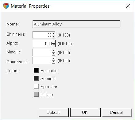
Figure 2. - Add
- Opens the Material Properties dialog where you can add a new material to the palette
- Defaults
- Use the default settings for color and material.
- Auto Color
- If you load a model that consists of only one color, click Auto Color to color the model according to HyperView's specifications.
Note: See the *BeginPalette() statement for more information on defining a material
palette.
Assign a Color to an Entity
Assign a Material to an Entity
Exclude Entities from Fitting
- From the Entity Attributes panel, select an entity from the entity list tree or pick an entity from the screen.
- For Use in fit, click Off.
Include Entities from Fitting
- From the Entity Attributes panel, select an entity from the entity list tree or pick an entity from the screen.
- For Use in fit, click On.