The Tree panel is the main control in HyperCrash where many essential functions are conducted.
Button
|
Behavior
|

|
to expand or collapse the tree.
|

|
to select or unselect all the parts in the tree.
|
|
Click the part line or assembly line in the listing window to select parts or assemblies. Several parts and assemblies can be selected using the SHIFT, CTRL, or SHIFT+CTRL keys.
|

|
to reverse the current tree selection.
|

|
to search a part in the tree by its name, ID, etc.
|

|
to add the selection in the graphic window.
|

|
to add the selection and fit it in the graphic window.
|

|
to remove the selection in the graphic window.
|

|
to isolate the selection in the graphic window.
|

|
to isolate the tree selection with transparency.
|
How do I...
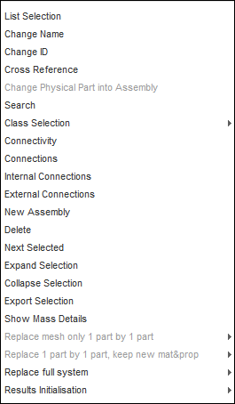
The context menu can be activated by right-clicking the mouse button.
| 1. | Place the mouse cursor in the Tree window. |
| 2. | Select part(s) and/or subset(s) in the tree. |
| 3. | Click the right mouse button. |
| 4. | Make a selection from the context menu that appears. |
|
To Display:
| 1. | In the Tree window, select parts and/or assemblies. |
Several parts and assemblies can be selected using the SHIFT, CTRL, or SHIFT+CTRL keys, or by left-clicking on a selection and dragging the mouse pointer over other parts and assemblies.
| 2. | Open the context menu (right-click mouse button) and select List Selection. |
The Selection List window appears, as shown below.
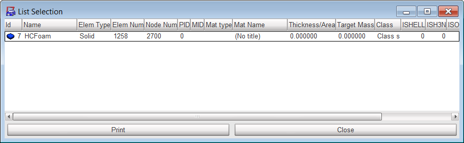
| • | Id: part or assembly identification number |
| • | Name: part or assembly name |
| • | Elem Type: type of element (solid, shell, spring, truss, beam, etc.) |
| • | PID: property identification number |
| • | MID: material identification number. (Springs and rivets have no material). |
| • | Mat Type: RADIOSS material law (law 2, law 27, law 36, etc.). (Springs and rivets have no material). |
| • | Mat Name: material name. (Springs and rivets have no material). |
| • | Thickness/Area: part thickness for shell elements, cross section for beam and truss elements. |
| • | Target Mass: theoretical mass of the part. |
| 3. | Click the top of desired column to sort the selection list by Id, Name, ..., etc. |
| 4. | Click Print to print the Selection List information. |
| 5. | Click Close to close the Selection List window. |
To Edit:
It is possible to make modifications from within the Selection List window by right-clicking on one or several parts listed, as shown below.
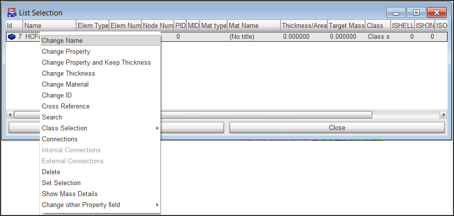
| 1. | Select one or several parts and/or subsets, and: |
| • | Change the name of the part |
| • | Change the property of the part(s) or assembly(ies)* |
| • | Change the material of the part(s) or assembly(ies)* |
| • | Open the search function |
| • | Set the selection in the tree |
| • | Show the mass detail of the selected part |
* The properties or material of the parts under the assembly will be changed.
|
| 1. | Open the context menu (right-click mouse button) and select Search or click the Search in Tree icon . |
| 2. | Select the Assembly, Part or Subpart tab. |
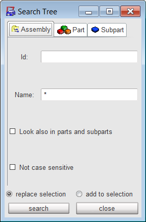
| 3. | Enter parameter(s) in a field (or several fields) according to the desired search. |
| 4. | Toggle the replace selection radio button to replace the tree selection; or |
Toggle the add to selection radio button to complete the tree selection.
| 5. | Click search to search the part(s) or assembly(ies) in the tree. |
| 6. | Click close to close the window. |
|
| 1. | In the Tree window, select parts and/or assemblies. |
Several parts and assemblies can be selected using the SHIFT, CTRL, or SHIFT+CTRL keys.
| 2. | Right-click the mouse button to open the context menu, select Class Selection. |
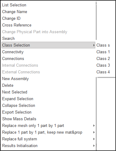
| 3. | Select one of the following: |
| • | Click Class s to apply a standard mesh class. |
| • | Click Class 1 to apply a fine mesh class 1 (most severe criteria). |
| • | Click Class 2 to apply a mesh class 2. |
| • | Click Class 3 to apply a mesh class 3. |
| • | Click Class 4 to apply a coarse mesh class 4 (least severe criteria). |
The mesh criteria and limits are defined in the file $hc/.hc_criteria.
|
| 1. | In the Tree window, select parts and/or assemblies. |
Several parts and assemblies can be selected using the SHIFT, CTRL, or SHIFT+CTRL keys.
| 2. | Click the Isolate Tree Selection icon to see only the selection in the graphic window. |
| 3. | Open the context menu (right-click mouse button) and select Connectivity. |
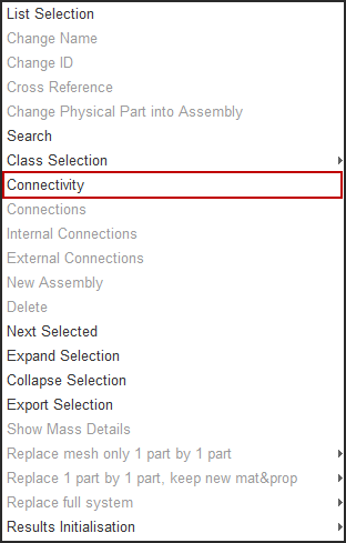
The graphic window displays the parts connecting the following items to the selected ones:
| • | connections (spotwelds, bolts, glue, welding line, hemming) |
| 4. | Answer the question in the dialog menu bar. |
|
Part connections (spotwelds, glue, bolts, hemming, welding line)
| 1. | In the Tree window, select part(s). |
Several parts can be selected using the SHIFT, CTRL, or SHIFT+CTRL keys.
| 2. | Open the context menu (right-click mouse button) and select Connections. |
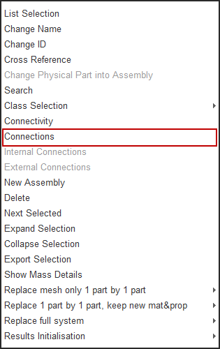
| 3. | In the Tree window, select assembly(ies). |
| 4. | Open the context menu (right-click mouse button) and select Internal Connections to find the connections between the parts in the selected assembly(ies). |
or
Open the context menu (right-click mouse button) and select External Connections to find the connections of the selected assembly(ies) with the rest of the model.
In the Notebook lower part window, the part(s) selected, their connections (bolts, spotwelds), and the connected parts are listed.
| 5. | In this window, select part(s) and/or connection(s). |
| 6. | Click the right mouse button to open a pop-up menu and select one of the following: |
| • | Click Display Selection to display the selected parts and connections in the graphic window. |
| • | Click Display All to display all the listed parts and connections in the graphic window. |
| • | Click Undisplay Selection to remove the selected parts and connections from the graphic window. |
| • | Click Undisplay All to remove all the listed parts and connections from the graphic window. |
| • | Click Clear Tree to remove the parts and connections from the Notebook lower part window. |
|
Move parts or assemblies from one assembly to another
| 1. | In the Tree window, select parts and/or assemblies. |
| 2. | Using the middle mouse button, drag this selection into the destination assembly. |
Create a new subset (new assembly)
| 1. | Open the context menu (right mouse button) and select New Assembly. |
A Change Name dialog appears.
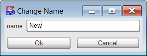
| 2. | In the name field, enter the new assembly name. |
| 3. | Click Ok to validate the name modification; or |
Click Cancel to cancel the name modification.
Change a name (for a part or an assembly)
| 1. | Open the context menu (right mouse button) and select Change Name. |
A Change Name dialog appears.
| 2. | In the name field, enter the new name. |
| 3. | Click Ok to validate the name modification; or |
Click Cancel to cancel the name modification.
Switch from physical part to assembly
| 1. | Select a physical part. |
| 2. | Open the context menu (right mouse button) and select Change Physical Part into Assembly. |
|
Another control is the Model Browser (from the Model menu, select Browser). The Model Browser allows you to view all the objects (parts, materials, properties, node groups, any include files, etc.) that belong to a model in a flat view or an expandable/collapsible list.
See also
Edit Material, Property and Thickness
Delete Parts
Export Parts
Replace Parts


