Feko is a comprehensive electromagnetic solver with multiple solution methods that is used for electromagnetic field analyses
involving 3D objects of arbitrary shapes.
EDITFEKO is used to construct advanced models (both the geometry and solution requirements) using a high-level scripting language
which includes loops and conditional statements.
One of the key features in Feko is that it includes a broad set of unique and hybridised solution methods. Effective use of Feko features requires an understanding of the available methods.
Feko offers state-of-the-art optimisation engines based on generic algorithm (GA) and other methods, which can be used
to automatically optimise the design and determine the optimum solution.
Feko writes all the results to an ASCII output file .out as well as a binary output file .bof for usage by POSTFEKO. Use the .out file to obtain additional information about the solution.
CADFEKO and POSTFEKO have a powerful, fast, lightweight scripting language integrated into the application allowing you to create
models, get hold of simulation results and model configuration information as well as manipulation of data and automate
repetitive tasks.
CADFEKO and POSTFEKO have a powerful, fast, lightweight scripting language integrated into the application that allows you to create models,
get hold of simulation results and model configuration information and much more.
With this card a voltage source is placed at a node between two segments or between a segment and a triangle, ground plane
or polygonal plate. It is mostly used to feed wires attached to plates.
This card realises excitation by a magnetic ring current (TEM-frill) on a segment. It gives an an accurate model of a
coaxial feed, but requires both the inner and outer radii.
This card specifies a voltage source on an edge between two triangles or at a connection between a single triangle and
a PEC ground plane or UTD plate.
This card is used to create a FEM modal excitation, which is the fundamental mode of the associated, infinitely long guided
wave structure of the modal port.
This card inputs data from a .rsd file containing the geometry of a transmission line or PCB structure and the current distribution along this line or
on the PCB for one or more frequencies.
This card defines a uniform electric current filament impressed between two arbitrary points inside of the FEM region (it does not have to coincide with the edges of tetrahedra). This can be used to excite for instance a patch antenna.
This card defines a planar, cylindrical or spherical aperture of measured or calculated field values that is converted
by PREFEKO internally into an equivalent array of electric and magnetic dipoles (A5/A6 cards).
The AS card defines an excitation by means of impressed spherical modes which are either radiating (propagating in positive
r direction to infinity, with r being the radius in a spherical coordinate system) or incident onto a structure (propagating
towards the origin r = 0).
The AW card is a two line card which is used to define a waveguide port excitation. With this card a waveguide port excitation
by an impressed mode on a rectangular, circular, or coaxial waveguide, can be modelled or the impressed travelling modes
in all waveguides of a multi-port network can be imported from a .fim file.
This card defines a ground plane with the reflection coefficient approximation (at z = 0). All computations that follow
this card will include the ground plane.
The CA card is used to define a section of a shielded cable which is used for irradiation (for example, computing induced
currents and voltages at the cable terminals) due to external sources. Transmission line theory is applied, for example,
no need to discretise the cable as with the MoM. A section is defined as a straight part of a cable (one cable can consist of multiple sections).
The CM card is used to couple Feko with the transmission line simulation programs CableMod or CRIPTE or the PCB tool PCBMod to calculate the coupling
of electromagnetic fields into transmission lines. (The AC card is used for the case of radiation by these lines.)
This card controls the export of data to additional ASCII files. For example the currents can be exported to the .out file or S-parameters can be exported to a Touchstone file.
This card can be used to define the frequency dependent or independent material characteristics of a dielectric medium,
metallic medium or an impedance sheet.
The EE card requests an a-posteriori error indicator whereby Feko can test the solution against an unconstrained physical test. The result is to give an indication of the region where
local mesh refinement should be considered.
This card includes the complexities of dielectric environments using special Green's functions. The Green's functions
relates the fields in space to the sources.
With this option the dielectric properties for the entire problem space can be set. This is useful for modelling in a
homogeneous medium that differs from free space.
This card defines a complex load to any non-radiating network port that is not connected to geometry (that is any non-radiating
network of the type Internal).
This card specifies an offset for the origin of the coordinate system for near and far field calculations. It also facilitates
using only a part of the structure through label selection when calculating fields.
This card defines the phase shift of the excitation between one unit cell and the next for periodic boundary conditions. The unit cell for a PBC calculation is specified with the PE card.
This card defines a skin effect, ohmic losses or an arbitrary user defined impedance boundary condition on wire segments
and surface elements. Layered dielectrics can also be defined.
This card is used to define the dielectric properties of each of the windscreen glass layers. These layers are placed
over the antenna elements by defining the relative position of the top layer to the reference plane.
When meshing a model, you can either use the automatic meshing algorithm to calculate the appropriate mesh settings
or you can specify the mesh sizes. When you specify the mesh sizes, the mesh sizes should adhere to certain guidelines.
Feko integrates with various products within HyperWorks such as HyperStudy. Integration with third-party products is also supported through the powerful scripting and plug-in infrastructure.
Feko creates and uses many different file types. It is useful to know what is stored in the various files and weather they were
created by Feko and if it is safe to delete them. The files are grouped as either native files that have been created by Feko or non-native files that are supported by Feko. Non-native files are often exported by Feko even if the formats are not under the control of the Feko development team.
A list of notes, errors and warnings are provided as reference and to provide more information regarding the reason for
the message and how to resolve the problem in the model.
This card includes the complexities of dielectric environments using special Green's functions. The Green's functions
relates the fields in space to the sources.
With this option a layered dielectric sphere located at the origin is taken into
account with the Green’s function.
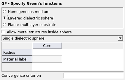
When this Green’s function is selected, the EM interaction of
a layered dielectric sphere located at the coordinate system centre is taken into account.
With this option it is, for example, possible to analyse a mobile phone in front of a
spherical shell model of the human head very efficiently.
Parameters:
Configuration list
The drop-down list allows selecting between a Single
dielectric sphere, a Core and a coating layer and a
Core and three layers.
Note: If metal structures are included,
the only options are Single dielectric sphere and
Core and two layers.
Allow metal structures inside sphere
When this item is checked metallic structures can be present in the inner parts of the
sphere.
Convergence criterion
Convergence criteria for the summation of the rows of Green’s functions. If this field
is 0 or undefined, a sensible standard criterion is used.
Radius
Radius of the sphere / layer in metres (is scaled by the SF card). For the layers,
this is the total radius of the core plus layers up to that point. The highest numbered
layer is on the outside of the sphere.
Material label
Label of the material (as defined in the DI card) to be used for the core /
layer.
The scaling factor that is entered by the SF card is applied
to the radius. Note that the surrounding medium is defined by material label “0”. By
default the values of free space is used, but these parameters can be redefined in the DI
card.
The Green’s function for a homogeneous or layered dielectric sphere can be used with
metallic structures (treated with the MoM) either inside or
outside the sphere (but not for example a wire from inside to outside). It can be used with
dielectric bodies treated with the volume equivalence principle (for example the hand of a
user around a mobile phone), but the dielectric bodies must be outside the sphere.