Add highlighting or illustrations to the scenario database.
Additional database objects can be added such as rectangles, lines, polylines, circles and
text and do not influence the computation. The Additional Data Tool can be accessed by
selecting Project > Additional Data from the Project menu or by pressing the
corresponding button on the Project toolbar.
Additional data objects can be stored in different layers, which can be enabled or disabled
for visualization separately. Currently additional data objects can be shown in the 2D View
only.
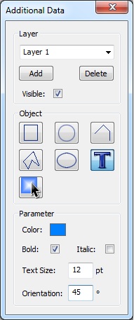
Figure 1. The Additional Data dialog.
Layer
The currently active layer can be selected using the drop-down list on top. The name of the active layer can be edited directly.
New layers can be added to the list by pressing the Add
button. An existing layer can be removed (together with all its content) by pressing
the Delete button.
Layers can be shown or hidden using the Visible check
box.
Object
The type of object to be inserted with the mouse can be selected in this
section.
Rectangle
Two opposite corner of the rectangle have to be defined by pressing the
left mouse button.
Polygon
Definition points can be inserted by clicking the left mouse button.
Pressing the right mouse button will close the polygon by connecting the
first and the last definition point.
Circle
The first click with the left mouse button defines the center of the
circle. The second click with the left mouse button defines the radius.
Ellipse
The two vertices of the ellipse can be defined with the first and the
second click with the left mouse button.
Line / Polyline
Definition points can be inserted by clicking the left mouse button.
Pressing the right mouse button will finish the input for this object.
Text
The first click with the left mouse button defines the position of the left
corner of the bottom line, thus the starting position for the text input.
The text to be displayed can be specified using the keyboard. The second
click with the left mouse button finishes the text input.
Selection Tool
Already available objects corresponding to the currently active layer can
be selected using the selection tool. Objects belonging to other layers than
the active one can not be selected. If an object is selected, a rubber band
will be displayed to indicate its bounding box.
To move an object, click the left mouse button near the rubber band and
keep the mouse button pressed while moving the mouse to the new object
location. Depending on the selected object, individual vertices can be
changed by clicking the left mouse button near the vertex to be
changed.
Color
The color of the object can be changed by clicking into the colored
rectangle.
Filled
If this option is enabled, the object will be displayed filled.
Bold
The inserted text will be formatted bold.
Italic
The inserted text will be formatted italic.
Line Width / Text Size
Width of lines or text size in points.
Orientation
Azimuthal orientation of object (counter clockwise rotation).
Note: All tools can be closed by pressing the Esc key on the keyboard. In this case the active
operation will be canceled and the Selection Tool will be activated.