Fillets
Create fillets or chamfers along an edge.
Fillet Edges
Round edges to create fillets with a constant radius.
-
On the Geometry ribbon, select the
Fillet Edges tool.

-
Select Apply
 on the microdialog.
Features are automatically retained and notches are preserved on sheets.
on the microdialog.
Features are automatically retained and notches are preserved on sheets.
Tip:
- By default, clicking an edge will also select all of its tangent edges.
Deselect Tangent Propagation
 in the microdialog to
disable this behavior.
in the microdialog to
disable this behavior. - If the fillet radius text box is highlighted red due to an invalid edge selection, press Ctrl+Z to undo or press Ctrl while clicking to deselect the edge. The previously valid selection will reappear.
- Change the default fillet radius in the Preferences.
Chamfer Edges
Create beveled edges.
-
On the Geometry ribbon, select the
Chamfer Edges tool.

-
Select Apply
on the microdialog.
Features are automatically retained and notches are preserved on sheets.
Tip:
- By default, clicking an edge will also select all of its tangent edges.
Deselect Tangent Propagation in the microdialog to
disable this behavior.
- Reverse the side the distance and angle are measured from by clicking
 in the microdialog.
 - If a distance/angle text box is highlighted red due to an invalid edge selection, press Ctrl+Z to undo or press Ctrl while clicking to deselect the edge. The previously valid selection will reappear.
- Change the default chamfer distance and angle in the Preferences.
Apply a Variable to a Parameter
Apply a variable to a parameter, or create a new variable on the fly from a tool microdialog.
You can apply existing variables and add new ones via the microdialog in various sketch and geometry tools.
-
In the tool’s microdialog, click the f(x) icon.
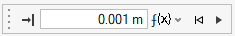
Figure 1. Example of a microdialog with a variable field
Tip:
- You can also create a variable by entering a new name and expression in the
microdialog’s text field, for example:
Variable1=50 - In addition, you can also create a new variable based on an existing
variable, for example,
Variable2=Variable1*0.5.
Keyboard Shortcuts & Mouse Controls
| To | Do this |
|---|---|
| Select features | Click |
| Append/remove feature selection | Ctrl+click |
| Delete selected feature | Delete+click |
| Delete selected filleted/chamfered face | Delete |
| Exit tool | Right-click and mouse through the check mark to exit, or double-right-click. |