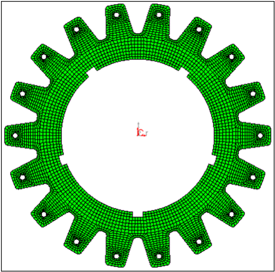
In this tutorial, you will update the mesh to a new geometry using
symmetry.
This exercise uses the fe_only.hm and
new_design.igs files, which can be found in the
hm.zip file. Copy the file(s) from this directory to your
working directory. Figure 1.
Open the Model File
In this step you will open the model files, fe_only.hm and
new_design.igs.
From the menu bar, select File > Open > Model and load the file, fe_only.hm.
From the menu bar select File > Import > Geometry and load the file, new_design.igs.
Create Domains and Handles
In this step you will create domains and handles.
From the menu bar, select Morphing > Create > Domains.
Switch the domain type from global domains to
3D domains.
Toggle the element selector to all elements.
Activate the partition 2D domains option.
Click create to create the domains.
Select return to exit the panel.
Create Symmetries
In this step, you will create symmetries.
From the menu bar, select Morphing > Create > Symmetries to enter the Symmetry panel.
Switch the symmetry type to cyclical.
Switch the symmetry angle from 180 degrees to
set freq.
Set the # of cycles to 18.
Click syst.
Select the center point of the gear.
Click domains >> all.
Click create.
Click return.
Morph the Mesh to New Geometry
In the step, you will morph the mesh to the new geometry.
From the menu bar, select Morphing > Morph, then select the move handles
subpanel.
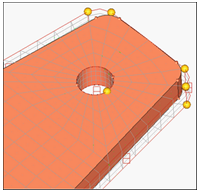
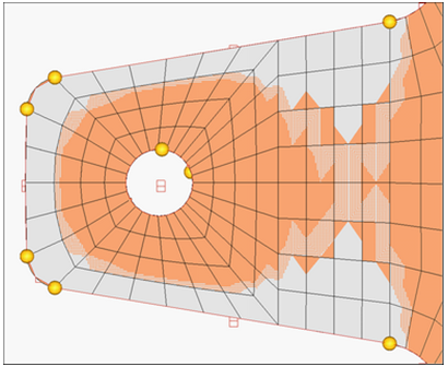
Zoom in to one of the cogs of the gear as in the following image.
Figure 2.
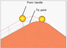
Switch the morphing method to move to point.
With from: handle active, select the node depicted in the following
image.
With to: point active, select the point on the geometry that you want to move
the handle to, as shown in the following image.
Figure 3.
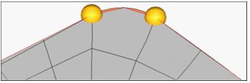
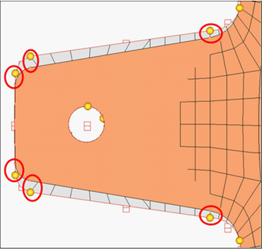
As the handles are moved, you will see that the mesh starts conforming to the
new geometry. Figure 4.
In the same manner, move the handles as shown in the following image.