HM-3510: Freehand Morphing
In this tutorial you will increase the length of a propeller blade by 100 units using freehand morphing.
This exercise uses the propeller.hm file, which can be found in the hm.zip file. Copy the file(s) from this directory to your working directory.
Load the Model File
In this step you will open the model file, propeller.hm.
-
Open the model file by clicking from the menu bar, or by clicking
 on
the Standard toolbar.
on
the Standard toolbar.
Morph the Blade
In this step you will morph the blade using method 1: Fixed value based.
-
Set the morphing method to translate.
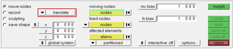
Figure 1. -
Use the moving nodes and fixed nodes selectors to select the nodes indicated in
the following image.
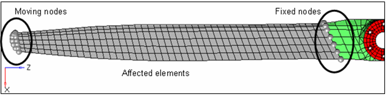
Figure 2.
Morph the Blade Method 2
In this step you will morph the blade using method 2: Interactive graphic manipulator base.
-
In the move nodes subpanel, set the morphing method to
manipulator.
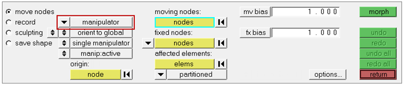
Figure 3. -
Use the moving nodes and fixed nodes selectors to select the nodes indicated in
the following image.
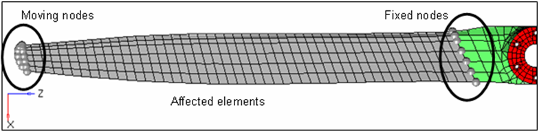
Figure 4. -
Use the affected elements selector to select the elements between the fixed
nodes and moving nodes. A manipulator appears.
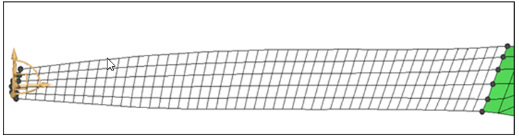
Figure 5. - Optional:
Move the manipulator to a different location by activating the origin: nodes
selector and selecting another node as the origin.
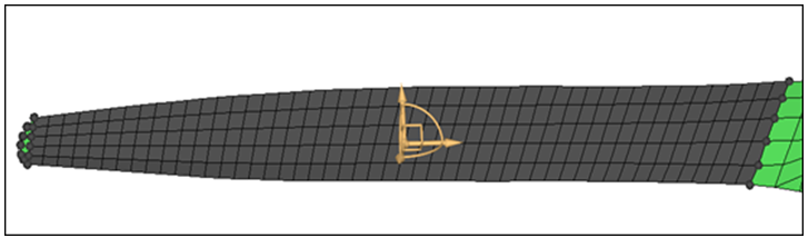
Figure 6. -
Zoom in and rotate close to the manipulator area.
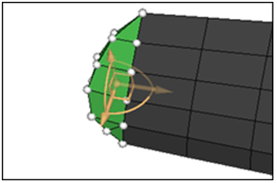
Figure 7. -
Translate the nodes by clicking and dragging one of the three yellow arrows of
the manipulator.
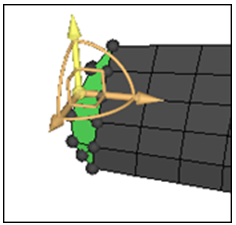
Figure 8. -
Rotate the nodes about the center of the manipulator by clicking and dragging
one of the three yellow arcs of the manipulator.
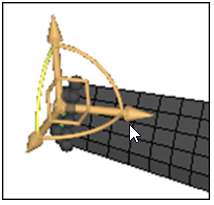
Figure 9. -
Move the nodes in a plane by clicking and dragging one of the three yellow
right angles of the manipulator.
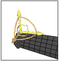
Figure 10. -
Create more than one manipulator at a time by setting the single
manipulator/multiple toggle to multiple.
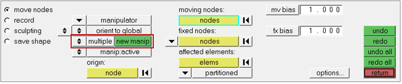
Figure 11. -
Make manipulators active or inactive by switching the
manip:active/manip:inactive toggle. When active, the manipulators morph the
model when you move them. When inactive, the manipulators will only change their
own position and orientation when you move them.
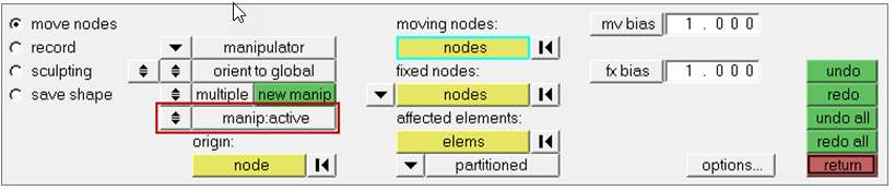
Figure 12.Method 2: The length of the propeller blade increased depending on how you dragged the handles along the three arrows, arcs, or right angles of the manipulator to respectively translate, rotate, or move the nodes. The fixed nodes did not move. The affected elements were stretched evenly to maintain element quality. The stretching of the elements took place between the moving nodes and the fixed nodes.