This exercise shows how to smoothly change the shape of a B-pillar via morph
volumes.
This exercise uses the body_side.hm file, which can be found in the
hm.zip file. Copy the file(s) from this directory to your
working directory. Figure 1.
Open the Model File
In this step you will open the model file,
body_side.hm.
Start HyperMesh Desktop.
To open the model file, click File > Open > Model from the menu bar, or click on
the Standard toolbar.
In the Open Model dialog, open the
body_side.hm file.
The model appears in the graphics area.
Create Morph Volumes
In this step, you will create morph volumes.
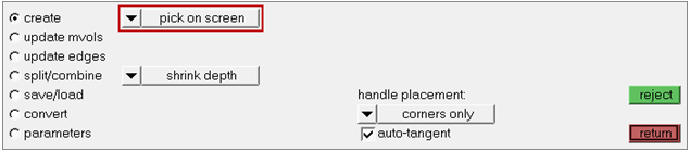
To open the Morph Volumes panel, click Morphing > Create > Morph Volumes from the menu bar.
Set the creation method to pick on screen.
Figure 2.
Set handle placement to corners only.
Select the auto-tangent checkbox.
On the Standard Views toolbar, click .
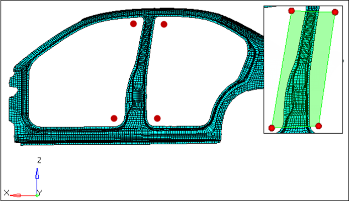
Click the four red circles indicated in the image below to draw a window.
HyperMesh creates a morph volume, which
encloses the area. Figure 3.
Split Morph Volume
In this step you will split the morph volume.
Go to the split/combine subpanel.
Set the by nodes/by edge toggle to by edges.
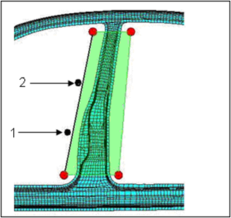
Select an edge of the morph volume close to location 1 as indicated in the
following image.
A green colored cross moves to the location of the black dot. Figure 4.
Click split.
The morph volume splits into two.
Repeat steps 3.3 and 3.4, except select an edge of the morph volume close to
location 2 as indicated in the previous image.
Change the Profile, Method 1
In this step you will change the profile of the b-pillar using fixed value based
method.
To open the Morph panel, click Morphing > Morph from the menu bar.
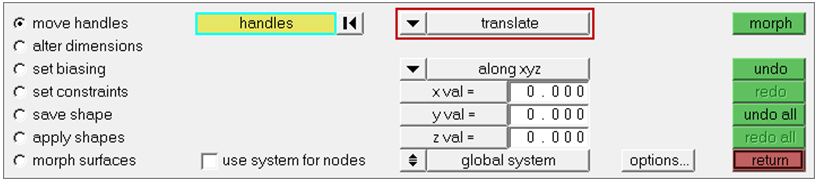
Go to the move handles subpanel.
Set the morphing method to translate.
Figure 5.
Set the orientation selector to along xyz.
In the y val= field, type 100.
Leave the x val= and z val= fields set to 0.
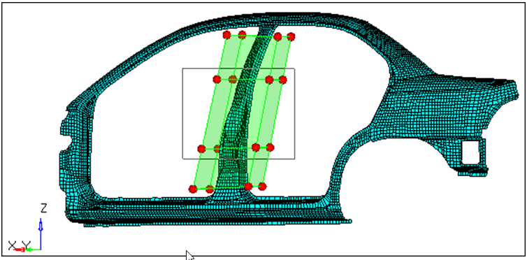
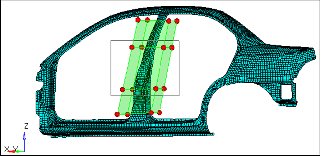
Press and hold Shift, then drag
your mouse around the eight handles indicated in the image below.
Figure 6.
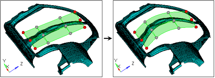
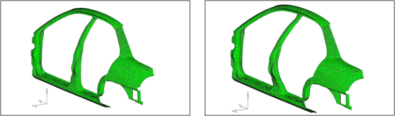
Click morph.
To verify that the b-pillar is morphed, rotate the model.
Figure 7.
To restore the model's original shape, click undo.
Change the Profile, Method 2
In this step you will change the profile using the interactive graphic manipulator
base method.
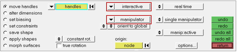
In the move nodes subpanel, set the morphing method to
interactive and
manipulators.
Figure 8.
Leave the other parameters and options set to their default values.
On the Standard Views toolbar, click .
Press and hold Shift, then drag your mouse around the
eight handles indicated in the image below.
A manipulator appears. Figure 9.
Optional: You can select another node as the origin to set the manipulator in a different
position.
Figure 10.
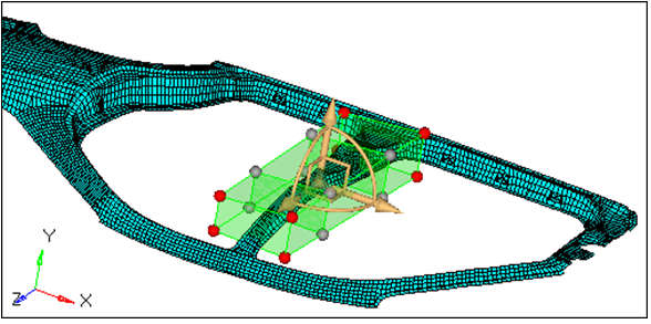
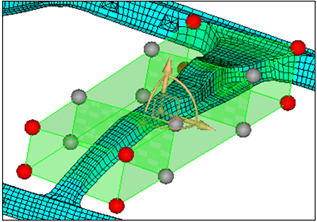
Zoom in and rotate close to the manipulator area.
Figure 11.
To translate the nodes, click and drag, graphically, one of the three yellow
arrows of the manipulator.
Figure 12.
click undo.
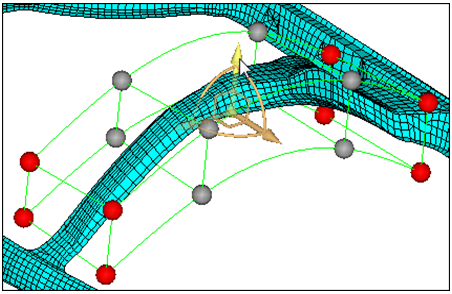
To rotate the nodes about the center of the manipulator, click and drag,
graphically, one of the three yellow arcs of the manipulator.
Figure 13.
Click undo.
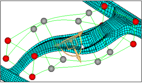
To move the nodes in a plane, click and drag, graphically, one of the three
yellow right angles of the manipulator.
Figure 14.
Click undo.
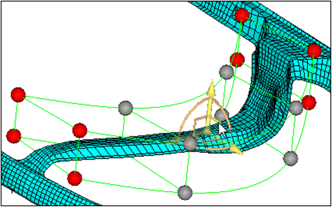
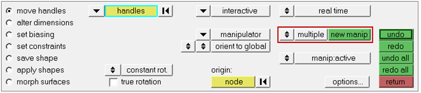
To create more than one manipulator at a time, set the single
manipulator/multiple toggle to multiple.
Figure 15.
To create a new manipulator, click new manip and then
graphically select one or more moving nodes.
Note: The different manipulators may have different selected entities and
different parameters, and can be moved independently of one another.
To move a manipulator, click a manipulator or simply move your mouse over a
manipulator.
HyperMesh updates the panel to the
parameters associated to that manipulator. You can change the parameters or the
entities associated with them if you desire.
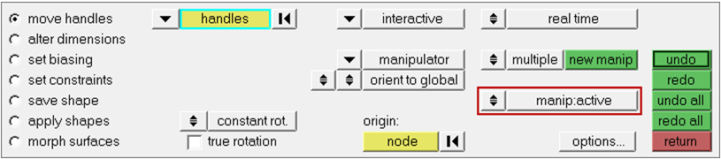
To make manipulators active or inactive, switch the
manip:active/manip:inactive toggle. When active, the
manipulators morph the model when you move them. When inactive, the manipulators
will only change their own position and orientation when you move them.
 on
the Standard toolbar.
on
the Standard toolbar.
 .
.