Turbulent Flow with Separation in an Axisymmetric Diffuser
In this application, AcuSolve is used to simulate fully developed turbulent flow through an axisymmetric diffuser with a divergent upper wall and a straight lower wall. AcuSolve results are compared with experimental results as described in Driver (1991) and on the NASA Langley Research Center Turbulence Modeling Resource webpage. The close agreement of AcuSolve results with experimental data and reference turbulence model performance validates the ability of AcuSolve to model cases with turbulent flow with separation due to an adverse pressure gradient within an axisymmetric geometry.
Problem Description
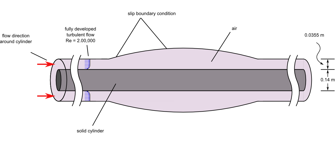
Figure 1. Critical Dimensions and Parameters for Simulating Turbulent Flow Through an Axisymmetric Diffuser
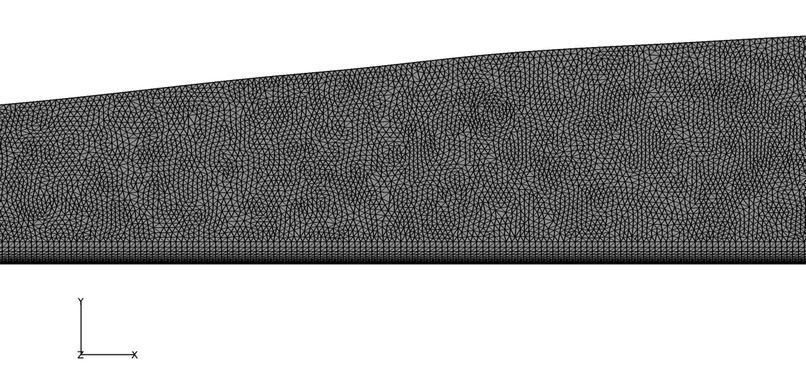
Figure 2. Mesh Detail Near the Divergence of the Walls in the Mesh used for Simulating Turbulent Flow Through an Axisymmetric Diffuser
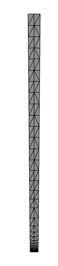
Figure 3. Cross Section (Perpendicular to Flow) of Mesh used for Simulating Turbulent Flow Through an Axisymmetric Diffuser
AcuSolve Results
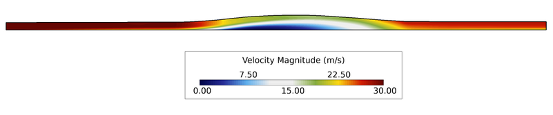
Figure 4. Velocity Contours Within the Diffuser
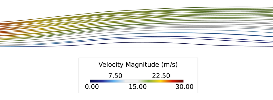
Figure 5.
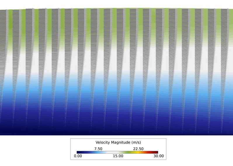
Figure 6. Close up View of Velocity Vectors and Contours in the Streamwise Plane Near the Reattachment Point
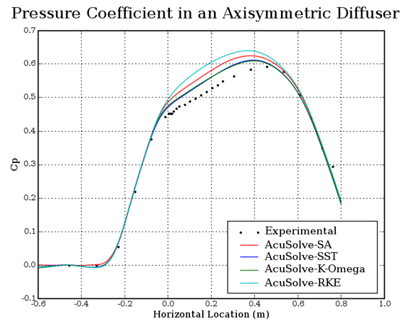
Figure 7. Coefficient of Pressure Along the Cylinder Wall Within the Diffuser Section (Horizontal Location = ~ 2.7m at the Midpoint of the Expanded Region of the Diffuser)
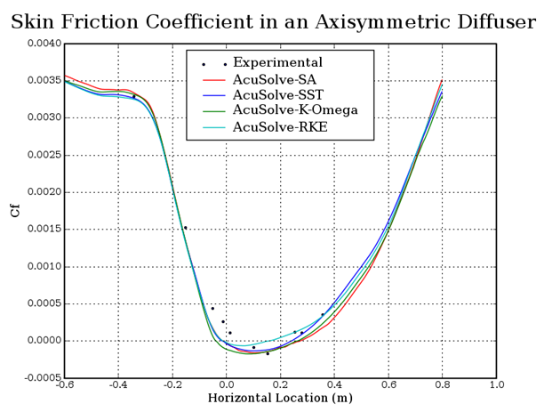
Figure 8. Skin Friction Coefficient Along the Cylinder Wall Within the Diffuser Section (Horizontal Location = 0 at the Point Where Flow Separation is Expected to Begin)
Summary
In this application, a fully developed turbulent flow at a Reynolds number of 2,000,000 is studied and compared against experimental data. The AcuSolve results compare well with the experimental data for pressure coefficient and skin friction coefficient. The recirculation region is slightly over predicted by the turbulence models studied, but the results still show a reasonable trend compared to experimental results. The performance of the three turbulence models was found to be consistent with previously published results for flow within an axisymmetric diffuser (NASA 2014). The results of this validation demonstrate the ability of AcuSolve to accurately predict flow recirculation with axisymmetric boundary conditions.
Simulation Settings for Turbulent Flow with Separation in an Axisymmetric Diffuser
AcuConsole database file: <your working directory>\axisymmetric_diffuser_turbulent\axisymmetric_diffuser_turbulent.acs
Global
- Problem Description
- Analysis type - Steady State
- Turbulence equation - Spalart Allmaras
- Auto Solution Strategy
- Max time steps - 150
- Relaxation Factor - 0.4
- Material Model
- Fluid
- Density - 1.0 kg/m3
- Viscosity - 1.5e-5 kg/m-sec
Model
- Fluid
- Volume
- Fluid
- Element Set
- Material model - Fluid
- Element Set
- Fluid
- Surfaces
- Axisymmetric_maxZ
- Simple Boundary Condition - (disabled to allow for periodic conditions to be set)
- Axisymmetric_minZ
- Simple Boundary Condition - (disabled to allow for periodic conditions to be set)
- Inlet
- Simple Boundary Condition
- Type - Inflow
- Inflow type - Velocity
- X velocity - 30.0 m/sec
- Turbulence input type - Direct
- Eddy viscosity - 1.5e-5 m2/sec
- Simple Boundary Condition
- Outlet
- Simple Boundary Condition
- Type - Outflow
- Simple Boundary Condition
- Slip_maxY
- Simple Boundary Condition
- Type - Slip
- Simple Boundary Condition
- Wall_minY
- Simple Boundary Condition
- Type - Wall
- Simple Boundary Condition
- Axisymmetric_maxZ
- Periodics
- Axisymmetric
- Periodic Boundary Condition
- Type - Axisymmetric
- Rotation Axis
- Point 1
- x-coordinate - 1.4 m
- y-coordinate - 0.0 m
- z-coordinate - 0.0 m
- Point 2
- x-coordinate - -1.5 m
- y-coordinate - 0.0 m
- z-coordinate - 0.0 m
- Point 1
- Periodic Boundary Condition
- Axisymmetric
References
D. M. Driver. "Reynolds Shear Stress Measurements in a Separated Boundary Layer Flow". AIAA Paper 91-1787 from the AIAA 22nd Fluid Dynamics, Plasma Dynamics, and Lasers Conference. Honolulu, HI. June 1991.
NASA Langley Research Center Turbulence Modeling Resource webpage, http://turbmodels.larc.nasa.gov/driver_val.html. Accessed December 2014.