Turbulent Flow Through a Pipe
In this application, turbulent flow of air through a pipe is simulated. AcuSolve results are compared with experimental results as described in White (1991) and extracted from the Moody chart. The close agreement of AcuSolve results with experimental results validates the ability of AcuSolve to model turbulent flow within pipes.
Problem Description
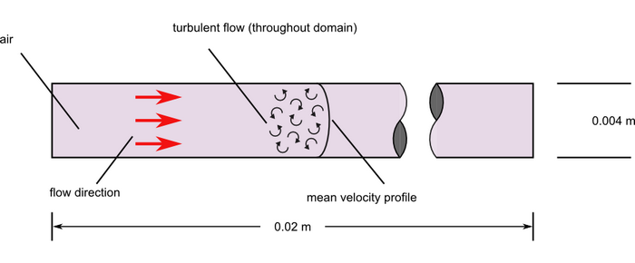
Figure 1. Critical Dimensions and Parameters for Simulating Turbulent Flow Through a Pipe
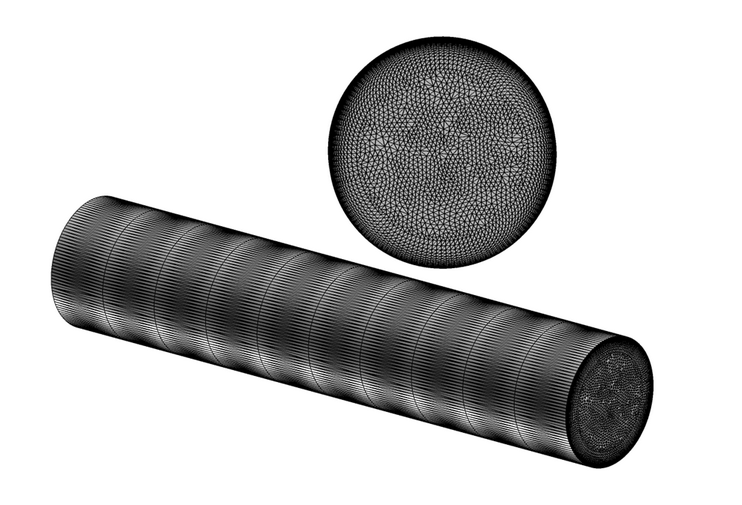
Figure 2. Mesh of a Periodic Segment Used for Simulating Turbulent Flow Through a Pipe
AcuSolve Results
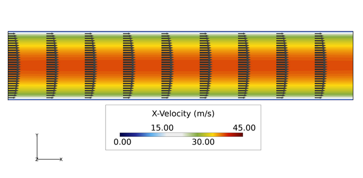
Figure 3. Velocity Contours and Periodic Velocity Vectors for the Averaged Turbulent Flow
| Experimental result | AcuSolve prediction | Percent deviation from experimental | |
| Average inlet velocity | 30.0 | 29.71 | 0.971 |
Summary
The AcuSolve solution compares well with the experimental result for average inlet velocity for turbulent flow through a pipe. In this application, the applied body force counteracts the change in pressure due to the viscous stresses near the pipe wall. The resulting friction factor for a smooth wall pipe and the specified Reynolds number is approximately 0.0326. With the imposed pressure drop defining the flow, the AcuSolve prediction of average inlet velocity is within 1.0 percent of the Darcy-Weisbach approximation.
Simulation Settings for Turbulent Flow Through a Pipe
AcuConsole database file: <your working directory >\pipe_turbulent\pipe_turbulent.acs.
Global
- Problem Description
- Analysis type - Steady State
- Turbulence equation - Spalart Allmaras
- Auto Solution Strategy
- Relaxation factor - 0.4
- Material Model
- Air
- Density - 1.225 kg/m3
- Viscosity - 1.781e-05 kg/m-sec
- Air
- Body Force
- dpdx
- Gravity
- X-component - 3739.98 m/s2
- Gravity
Model
- dpdx
- Volumes
- Fluid
- Element Set
- Material model - Air
- Body force - dpdx
- Element Set
- Fluid
- Surfaces
- Inlet
- Simple Boundary Condition - (disabled to allow for periodic conditions to be set)
- Outlet
- Simple Boundary Condition - (disabled to allow for periodic conditions to be set)
- Wall
- Simple Boundary Condition
- Type - Wall
- Roughness height - 0.0 mm
- Simple Boundary Condition
- Inlet
- Periodics
- Periodic 1
- Periodic Boundary Condition
- Type - Periodic
- Periodic Boundary Condition
- Periodic 1
References
F. M. White. "Viscous Fluid Flow". Section 3-2.1. McGraw-Hill Book Co., Inc.. New York. 1991.
Experimental solution adapted from Darcy-Weisbach equation based on friction factor taken from the Moody chart with a Reynolds number of approximately 8,250.