Introduction of background knowledge regarding flow physics and CFD as well as detailed information about the use of AcuSolve and what specific options do.
Collection of AcuSolve simulation cases for which results are compared against analytical or experimental results to demonstrate the accuracy
of AcuSolve results.
Mesh attributes control various aspects of the mesh generation process, including mesh size. Mesh attributes can be
set on a global (whole model) and/or local (model entity) basis.
Mesh size can also be specified as a function of location. Geometric shapes such as spheres,
boxes and cylinders can be drawn and mesh sizes are specified for the volume enclosing these
Zone Mesh Attributes.
The Global Mesh Attributes represent mesh settings that are applied to the entire model. Additionally, the
size specified in this panel is used as the global mesh length scale that is used in the octree method when
evaluating all subsequent mesh sizes.
Every geometric model in AcuConsole contains one or more volume groups. The pipe example model has one volume group called fluid with one geometric
region.
Once the geometry is imported into AcuConsole, it will have one or more surface groups. Each of the surface groups could have one or more geometric faces
associated with it.
The Mesh size type for Surface Mesh Attributes can be Absolute, Relative, Absolute Expression, Relative Expression,
Absolute Anisotropic, Relative Anisotropic or None.
If the Mesh size type is set to None, then AcuConsole uses the mesh size provided on the parent volume group and the Global Mesh Attributes to determine the mesh
size on the face.
The Curvature refinement parameters for a surface work in the same way as the ones used in Volume Mesh Attributes. The only difference is that they are applied on each of the geometric faces in the surface group.
Boundary layer parameters can only be applied in the Mesh Attribute panel for surface groups. To activate boundary
layer specification, the Boundary layer flag must be turned On.
Once the geometry is imported into AcuConsole, it will have one or more surface groups. Each of the surface groups could have one or more geometric faces
associated with it.
If the Mesh size type is set to Relative, the Relative mesh size has to be
specified.
The actual mesh size will be computed by multiplying the Relative mesh size with the largest edge
length of the bounding box for each geometric face in the surface group. Note that
this means a different mesh size may be used for each face in the surface group.
Example
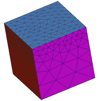
This example will use the same box as used in the Absolute surface mesh example. Here
the mesh on surface "One" is prescribed by a relative mesh size. The relative mesh
size of 0.125 is used. Since the largest length in the model is one meter, this is
multiplied by 0.125 to generate a surface mesh where the largest element is 0.125
(1*0.125= 0.125). The resulting mesh is shown below.