Extrusion Mesh Attributes
Extrusion meshing is a technique in which structured mesh is created in volume and on surface entities.
This meshing approach can be combined with standard unstructured meshing techniques within a single model. This provides a powerful method of efficiently meshing anisotropic features, while still retaining the simplicity and ease of an unstructured mesher. It is also useful in applications where some of the components have very high aspect ratios and the particular component can be modeled with high-aspect ratio elements. The extrusion mesh interface allows you to generate extruded mesh regions by specifying the source and destination entities for the extrusion. Two different types of extrusions are supported: volume extrusion and surface extrusions.
Volume Extrusion
A volume extrusion creates volume elements by extruding a specified beginning surface to a specified ending surface using either a number of layers or a desired spacing between extruded elements.
Below is an example of using the volume extrusion mesh. The model consists of a pipe with an inflow, outflow and wall surface. Below is an image of the pipe model.
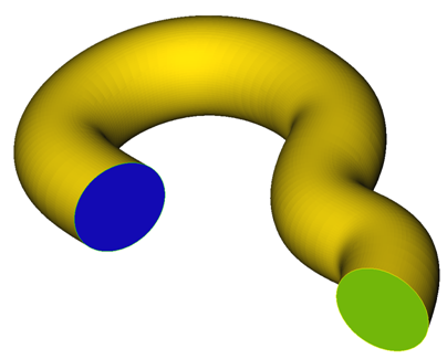
Figure 1.
The surface "wall" is provided with boundary layer mesh attributes. The Mesh size type is set to none, as to not over specify the surface mesh.
To create a mesh extrusion, right-click on Mesh Extrusions in the Model Tree and select New.
The extrusion can be renamed by right-clicking on the new extrusion and selecting Rename. The mesh extrusion is defined by right-clicking on the extrusion and selecting Define.
Once Define is selected a Mesh Extrusion Dialog Box will appear. This dialog is where the extrusion will be defined. The first selection is the geometry type. Here you will specify a surface to create a volume extrusion or an edge to create a surface edge extrusion. First you will create a volume extrusion by selecting a surface to extrude.
The next step is to define the beginning and ending surfaces for the extrusion, specified by Side 1 and Side 2. All of the surfaces present in the model will appear in the drop down menu. Here the surface which will extruded can be selected or it can be selected interactively by selecting the eye ball next to the drop down bar. Once the eye ball is selected a dialog box will appear and the surface can be selected.
Once the surfaces have been selected the extrusion type can be selected, which specifies to use either the number of layers or layer height for the extrusion.
For this example the number of layers is specified, using 50 layers to go in-between the Inflow surface to the Outflow surface. The extrusion options specify the element type as either mixed elements or all tetrahedral elements.
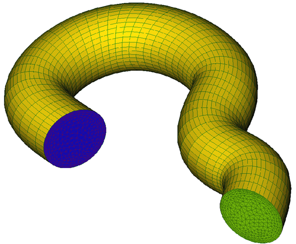
Figure 2.
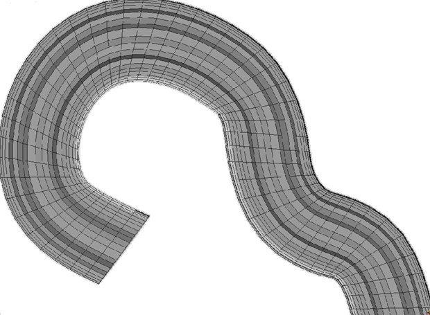
Figure 3.
Edge Extrusion
An edge extrusion creates a surface mesh between two specified edges. The mesh on the edge is computed then propagated along a surface to the ending edge. The number of edges on the beginning edge must be the same as are on the ending edge. Below is an example using the same pipe model as the surface extrusion example.
The edges in the model which will be used for the extrusion has to be specified in the same manner as surfaces in the above example. Unless otherwise specified, all of the edges in the model are added to a default edge group, named default. Add new edges by right-clicking on Edges and selecting New. Right-click on the new edge specification and select the edges which will be used in the extrusion.
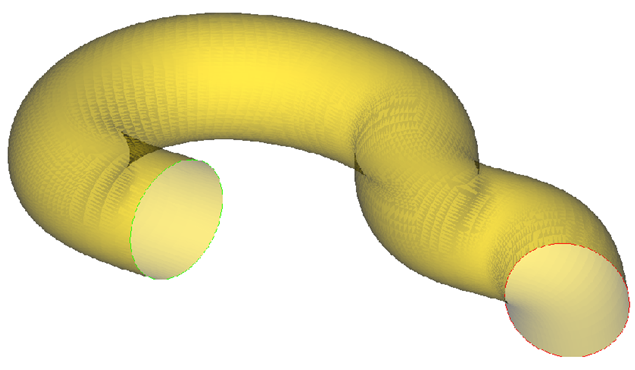
Figure 4.
The mesh extrusion is generated by right-clicking on Mesh Extrusion and selecting New. In Geometry type, edge is selected since we are generating a surface mesh using edges.
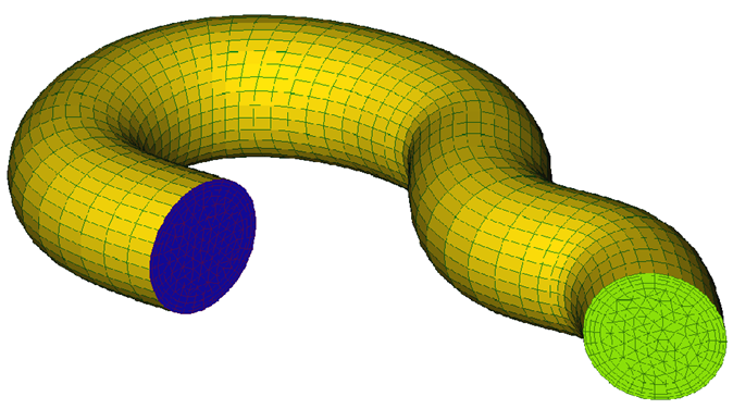
Figure 5.
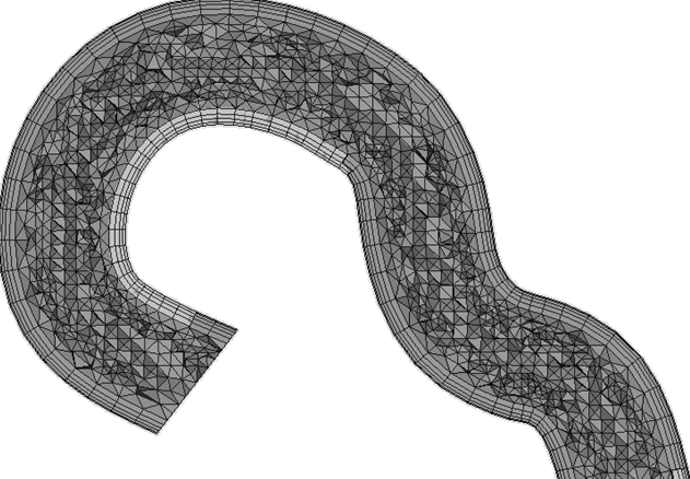
Figure 6.