Open the Part Browser
Use the Part Browser to create, organize and manage the CAE part structure/hierarchy.
By default, the following attributes are listed as columns.
Add or remove columns by right-clicking on a column and checking/unchecking the appropriate attribute.
- Entity
- List of the Model, Part Assemblies, Parts and Components. By default the browser is displayed in Hierarchical View.
- Color
- Displays the Component and Part entity colors.
- UID
- Displays the Part Assembly and Part Unique IDs.
- Revision
- Displays the Major revision, Study revision, and Library Part revision.
- Representation
- Displays the in-session/loaded representation.
- Active
- Displays the Part entity active status.
For a full description of usage, refer to Manage Configurations.
- CID
- Displays the entity specific Component ID’s. At the Part level it displays IDs for owned components. At Component level it shows the ID of components.
- PID
- Displays the entity specific Property ID’s. At the Part level it displays IDs for referenced properties. At Component level it shows the ID of the referenced property.
- MID
- Displays the entity specific Material ID’s. At the Part level it displays IDs for referenced materials. At Component level it shows the ID of the referenced material.
- Material
- Displays the material name.
- Thickness
- Displays the entity specific thickness. At the Part level it displays the thicknesses of the referenced properties. At Component level it shows the thickness of the referenced property.
- PDM PID
- PDM Property ID metadata.
- PDM MID
- PDM Material ID metadata.
- PDM Material
- PDM Material name metadata.
- PDM Thickness
- PDM Thickness metadata.
- PDM MeshFlag
- PDM Mesh metadata (not case sensitive).
- PDM Variant Condition
- If non-empty, displays the part that is used as a variant in one or multiple part configurations. It is user editable in the Entity Editor.
- PDM Variant Scope
- Along with the Variant Condition attribute, displays which part configurations the part belongs to as a variant. It is user editable in the Entity Editor.
View Modes

Figure 1.
- Entity View. Displays a single view in the browser for parts or subsystems.
- Set View. Splits the browser into two views: Entity View and Set View. In the Set View you can create, organize and manage part and subsystem sets.
- Configuration View. Splits the browser into three vertical views: Configuration, Set and Entity View. In the Configuration view you can create, organize and manage configurations.
- Configuration View, Split Left. Splits the browser into three views: Configuration, Set and Entity View. In the Configuration view you can create, organize and manage part configurations and subsystem configurations.
Part View Modes

Figure 2.
- Hierarchical Part View. Displays all entities, including components, in a
hierarchical view.
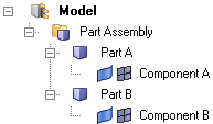
Figure 3. - Flat Part View. Displays all entities, with the exception of components, in
a flat list. Part Assemblies and Parts are logically grouped into their own
collectors.
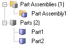
Figure 4.For example, in Flat View, you can use the Query Builder to isolate part entities. In the example BOM shown above, setting the entity type filter to Part results in the following view.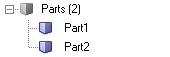
Figure 5.
Entity Editor
Edit part and component attributes in the Entity Editor.
Edits can be made for a single part or component or multiple parts and components. If a component is selected, the Entity Editor displays component specific attributes.
The attributes available in the Entity Editor vary based on the entity type selected.
Part/Part Assembly
- General Data
- Displays attributes that are unique to the part or assembly, including part/assembly name, Unique ID (UID), color, and include file, and Revision data.
- Representations Data
- Displays attributes that are specific to a part representation, such as representation name, file location, property ID, material ID/name, and thickness. These attributes are non-editable at the part level.
- Position Data
- Displays the 4 x 3 transformation matrix of a part, namely its translation, rotation, and scaling. These attributes are non-editable.
- PDM Data
- Displays PDM attributes that were parsed as metadata during the BOM importation, such as PDM ID, PDM Revision, PDM Variant Condition and PDM Variant Scope. This information, namely the PDM PID, PDM MID, PDM Material and PDM Thickness, is used to generate the initial component, property, and material cards upon creation of the common representation. These attributes can be used to cross-reference common and discipline specific mesh representation attributes.
Part Set
- General Data
- Displays attributes that are unique to the part set, including part/assembly name and ID.
- Part Assemblies / Parts Data
- Displays the number of parts organized into the selected part set.
- Part Sets Data
- Displays the number part sets organized into the selected part set.
Configuration
- General Data
- Displays attributes that are unique to the configuration, including name, and ID.
- Parts Assemblies / Parts Data
- Displays the number of parts organized into the selected configuration.
- Configurations Data
- Displays the number of configurations organized into the selected configuration.
- Part Sets Data
- Displays the number part sets organized into the selected configuration.
- Active
- Indicates the active/inactive state of the selected configuration. This attribute is non-editable. To activate a configuration, enable the configuration’s associated checkbox in the Active column of the Configuration view.
Workflow Batch
The Part Browser can be used to batch the model build workflow.
Model Build Workflow
- Importing BOM files (PLMXML, UDMXML or CAD BOM)
- Creating multiple representations
- Exporting UDMXML, delta PLMXML files, or Vizmockup PLMXML files (for PDTek use cases)
- Saving the monolithic HyperMesh binary on export
- Saving the representations to the connected part library
- Syncing metadata on export BOM
Create the Batch File
In this task you will create model build batch file.
Solver Specific Details
Abaqus
The complete set-up of Abaqus parts and instances format input files is supported.
Primary use cases:
- Import of a CAD geometry
- Import of an Abaqus parts and instances format input file
Import of a CAD Geometry
- Preference setting
- Upon opening HyperWorks, you can set the
user profile to Abaqus
Standard2D/Standard3D/Explicit via . Further, click Preferences in the
File menu and check the Part ID Management
option, as shown below.
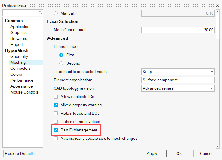
Figure 6. - Importing the CAD geometry and viewing in Part Browser
- Upon importing the CAD geometry with the Part ID Management preference
setting checked, you can open the Part Browser to
view the part and instance hierarchy.
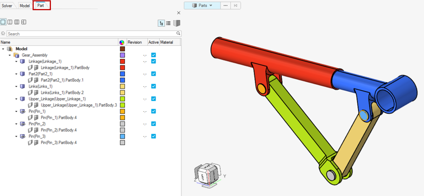
Figure 7. - Meshing Abaqus parts and instance format geometry
- Meshing parts individually is always recommended. When there are
multiple instances of the same part, it is crucial to mesh the first
instance of the part and synchronize the mesh to other parts. It is
always important to ensure that the part geometry that is meshed has the
mesh stored in its original component.
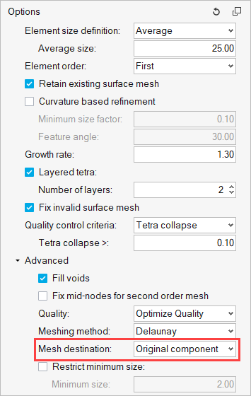
Figure 8. - Once the first instance of a part is meshed, a right-click option to
synchronize the mesh with other instances of the same part is available
in the Part Browser.
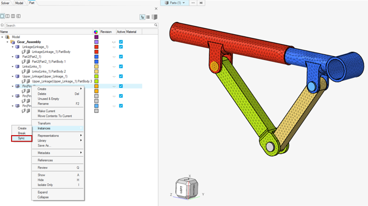
Figure 9. - Material
- Materials can be created in the Model Browser.
- Part content (Property, Sets, Surfaces, System, and so on)
- A double-click on any instance in the Part Browser will take it to an isolated part edit mode. Here, you can set up all the part content, such as a property with a material orientation system, sets, and surfaces that can be contained within a part. If the part has multiple instances in the model assembly, upon exiting the part edit mode, the changes and additions are automatically synchronized with other instances of the same part.
- It is only in this location that any part related content mentioned
above can be added in HyperWorks. A
right-click on the part in this mode will allow the creation of a
property and other part contained entities. Switching back to a
hierarchical part view or flat part view will automatically synchronize
the changes with other instances of the same part.
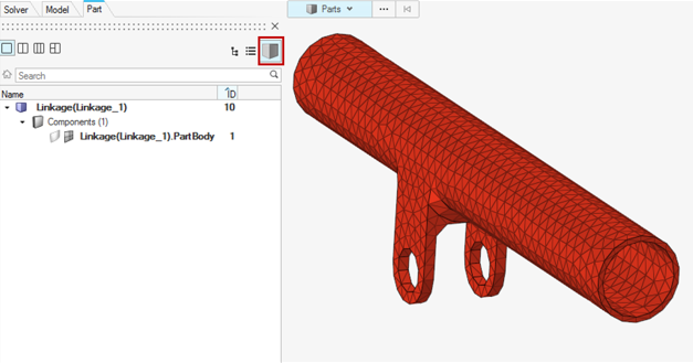
Figure 10. - Assembly and Root model content
- A right-click on Model allows a selection option to make the root model current. With the root model set as current, any surface, set, contact/tie, boundary conditions created using the Model Browser, panel, or any specific workflow tools like the Contact Browser creates entities in Assembly (outside of instances) or at root model (outside of Assembly) where it is relevant for the entity to remain.
- Analysis setup
- All the analysis conditions are a part of model level data (after *END ASSEMBLY). The corresponding model is set as current. Further, loads and boundary conditions can be created through panels with a load collector created for their use in the Model Browser. The Contact Browser is available to set up contact/tie between mating parts or components. Tie constraints created using the Contact Browser ensure that the keyword is placed at the Assembly level, as per the solver requirement. The analysis step can be defined using the loadstep manager. All these entities can also be created through the Model Browser or Solver Browser.
- Export
- Exporting a solver input file with Parts and Instances format requires
activating a checkbox in the solver export options, as shown below.
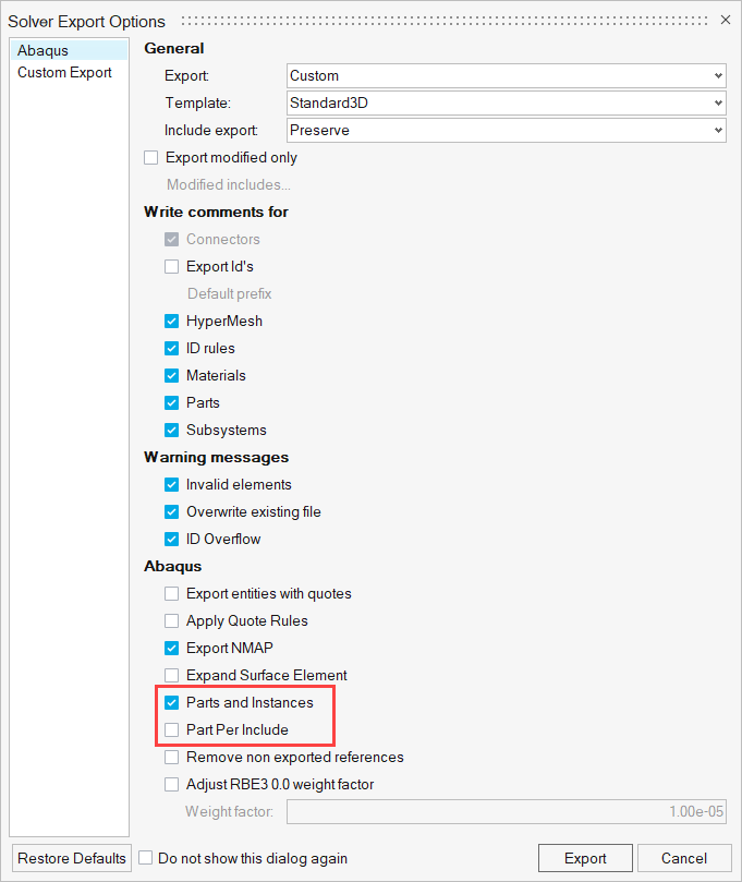
Figure 11.
Import of an Abaqus parts and instances format input file
Unlike CAD geometry, an Abaqus parts and instances format input file can be directly imported using the solver import options. There is no need to turn on the Part ID management. Further set-up of any analysis conditions can be defined using the options discussed above.
Limitations and Restrictions
- Entities defined at the instance level are not supported.
- Does not support the creation or export of new include files. Include files from the imported input file are preserved and cannot be modified.
- Analysis set-up is restricted to the following:
- Entities such as sets and surfaces cannot be created or edited in an instance. The same entities can be created at the assembly or part level.
- It is highly recommended not to use panels for any set-up except for loads and boundary conditions.