Import Parts, Part Assemblies, and Part Instances
- From the menu bar, click .
- Select a file that contains the parts, part assemblies, and part instances to import.
- Define additional options as needed.
- Click Import.
Import PDM Data
Import metadata from CAD to part. This facilitates visualizing CAD-centric metadata in the Part Browser and aids in the model build workflow.
-
If you selected Settings in Step 1:
- From the sub-menu, select Update or Mapping.
- The Update selection refers to the REM settings for part data and PDM data. You can choose whether to import only incoming data, or to keep both.
- The Mapping selection refers to mapping CAD
metadata to PDM attributes. These settings can vary depending on the CAD
format. The following figure is an example of PDM mapping settings for the
JT CAD reader.
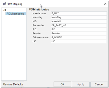 Figure 1.
Note: You can also access these settings by right-clicking in the part browser and selecting .