Use the Move tool to translate and
rotate selected entities.
Certain types of entities, like parts and assemblies, cannot be moved with the
Move tool. Entities like
pressures cannot be moved because their position and orientation are determined by the
entity to which they are applied.
From the Home tools, click the Move tool.
Figure 1.
Note: In HyperMesh, the Move tool is part of a ribbon group menu
along with the Transformation, Mirror, and
Scale tools. Click the arrow besides
the icon to view the tool if it is not currently active.
Optional: Click on the guide bar to define movement options.
Select an entity type using the guide bar selector.
Select entities to move.
The Move tool is placed the center of selected
entities.
Click a graphical manipulator then do one of the following:
Drag the graphical manipulator to translate or rotate entities in the selected direction(s).
Enter a precise value in the microdialog and
press Enter.
To
Do This
Translate along an axis
Click the X, Y, or Z arrow. Figure 2.
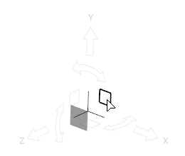
Translate along a plane
Click the XY, XZ, or YX plane square. Figure 3.
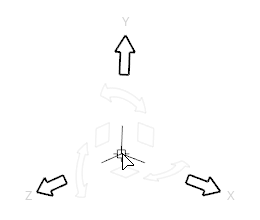
Translate freely in 3D space
Click the origin of the Move
tool. Figure 4.
Tip: Use the icons in the microdialog to align the tool to a
part or the global axes.
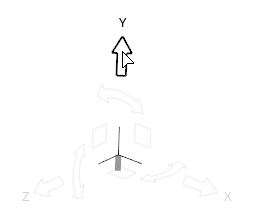
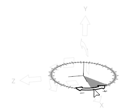
Rotate around an axis
Click a curved arrow. Figure 5.
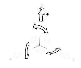
Rotate freely
Click at the tip
of the X, Y, or Z arrow and drag. Figure 6.
Tip: Use snap points to align entities by
clicking-and-dragging a snap point on one entity
to the snap point on a second entity.
Reposition the Move Tool
Reposition the Move tool along an axis, within a plane,
or in 3D space to change the center of rotation.
From the Home tools, click the Move tool.
Figure 7.
Note: In HyperMesh, the Move tool is part of a ribbon group menu
along with the Transformation, Mirror, and
Scale tools. Click the arrow besides
the icon to view the tool if it is not currently active.
Enter editing mode in the following ways:
Hold Shift.
Double-click one of the graphical manipulators.
The Move tool becomes orange, indicating
that it is ready to be repositioned.
Similar to translating and rotating, use the graphical manipulators and
microdialogs to reposition the tool.
Let go of Shift or left-click in empty space to exit editing mode.
The Move tool displays in
white.
Microdialog Options
Align the Move tool with the global axis.
Align the Move tool along an edge or face. If
the Move tool is being repositioned
(highlighted orange), clicking this button will force the Move tool to be aligned automatically as you drag it
around the model.
Collision Detection
Prevent components from passing through other components.
Note: Only available for components.
The default behavior of the Move tool allows components to
pass through each other and overlap uninhibited. Figure 8.
When the collision detection option is activated, an attempt to collide two
components by moving one of them results in the component stopping at or before the
point of collision. If you attempt to drag the component past this position, it
remains in the non-penetrating position and the feature edges of the component that
is blocking the motion are highlighted orange. If you continue to drag the component
all the way through the blocking component, the dragged component will move once
again until it encounters another collision. Figure 9.

 on the guide bar to define movement options.
 at the tip
of the X, Y, or Z arrow and drag.
at the tip
of the X, Y, or Z arrow and drag.