Wheel Posts
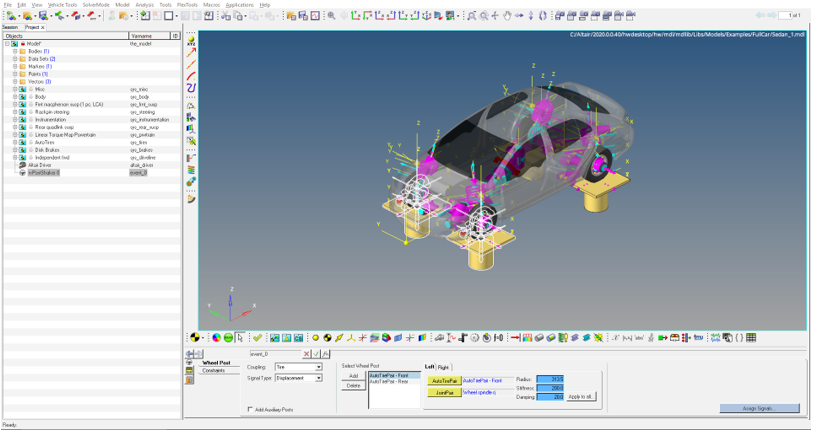
Figure 1. A Post is added for each AutoTire
Coupling
You can couple the wheel body of the AutoTire to the wheel post by using two methods:- Spindle Coupled
- The wheel body is constrained at the wheel center to the vertical motion of the wheel
post. The wheel body is free to move longitudinally, laterally and to rotate about any
direction relative to the wheel post.Note:
- The Wheel post connects to the ground by an orientation joint.
- The Wheel Body is connected to the Jack Body by an inplane joint.
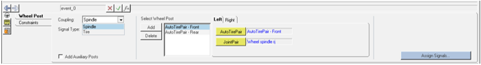
Figure 2. Spindle Coupling - Tire Coupled
- The wheel body attaches to the post via a linear stiffness and damping representing
the tire. The force in the stiffness and damping acts between the wheel body and the
post in the global Z direction. You enter the Radius, Stiffness and Damping as shown in
the panel. These parameters are used in an IMPACT function with the exponent value set
to 1.0. The function takes the following form with parameters plugged in:
`IMPACT( DZ({mrk_onWheel.idstring},{mrk_onJack.idstring},{mrk_onJack.idstring}),
VZ({mrk_onWheel.idstring},{mrk_onJack.idstring},{mrk_onJack.idstring}),
{ds_actData.real_tireRadius.value}, {ds_actData.real_tireStiffness.value}, 1.0,
{ds_actData.real_tireDamping.value}, 0.001)`
Use the ‘Apply to all’ option to update the Radius, Stiffness and Damping values in all wheel posts.
Note:- The Wheel post is constrained to the ground by an orientation joint.
- AutoTire systems are deactivated before exporting the solver input file.
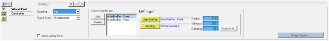
Figure 3. Tire Coupling
Signal Type
You can input Displacement, Force/Moment and Acceleration signals to wheel posts:- Displacement signals
- Force/MomentNote: If the ‘Add Wheel Reaction Forces’ option is checked, the reaction forces are calculated at the wheels, after the static simulation and added to the Z-direction force signal provided by the user. The force signal is applied to the Wheel Post and can be seen in the n-Post Signal Manager.
- Acceleration: Acceleration is first converted to displacement, following which the displacement is applied.
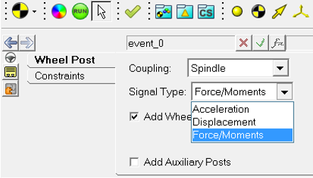
Figure 4. Signal Types
Other Panel Options
- If the tires in the vehicle are not ‘AutoTires’, you will have to manually add a Wheel
Post by using the ‘Add’ button in the panel. Using the ‘Delete’ button will delete the
chosen post.
Figure 5. Manually add a Wheel Post, in the absence of AutoTires - Each Wheel Post has three attachments Body, Point and Joint, similar to the Wheel Posts
added to the AutoTires.Note:
- Body and Point attachments are necessary for the inplane joint mentioned above under the Coupling section.
- The Joint attachment is used for locking the wheels.
- Add Auxiliary Posts: If you need to add posts to excite non-wheel parts of the vehicle, for example the chassis, to simulate aerodynamic forces, this option can be checked to add a new tab called the Auxiliary Post.
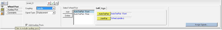
Figure 6. Various Panel Options