n-Post Signal Manager
- The Data Directory field is the location where the input signal files are stored. This allows the user to directly pick the input signal file in the steps that follow.
- For Displacement and Acceleration signal types, signal inputs in X, Y and Z directions can be entered.
- For the Force/Moment signal type, force inputs in X, Y, Z directions and moment inputs in X, Y, Z (MX, MY, MZ) directions can be entered.
- The input signal file is chosen by clicking on the folder icon under the ‘Drive File’ header.
- Supported file formats are .csv,.dac,.rsp and .rpc.
- When a file is chosen, the ‘Channel’ section is populated with the available signals in the file.
- If the input signal file contains more than one signal, the one to be applied must be selected.
- A scale and an offset for the signal, can be entered in the next two columns.
- The plot icon
 can be
used to plot the chosen signal with the given scale and offset.
can be
used to plot the chosen signal with the given scale and offset.
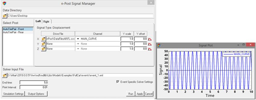
Figure 1. Click the Assign Signals Button for Displacement and Acceleration Options, Signal Plot
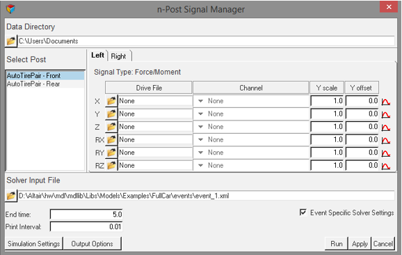
Figure 2. Click the Assign Signals Button for Force/Moment Options
Attention: After setting up the signals, the Solver Input File, End Time and Print
Interval can be provided, and the event can be simulated using the
‘Run’ button.
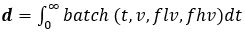
Conversion of Acceleration to Displacement
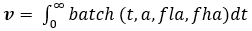
The measured acceleration signal is converted to displacement signal using the following relationship.
where,
 |
Time series data |
 |
Integrated displacement signal from filtered velocity |
 |
Integrated velocity signal from filtered acceleration |
 |
Measured acceleration data |
 |
Batch filter applied in a band of filter frequency |
 |
Lower bound acceleration filter frequency, 0.5 Hz |
 |
Higher bound acceleration filter frequency, 1000 Hz |
 |
Lower bound velocity filter frequency, 0.5 Hz |
 |
Higher bound velocity frequency, 1000 Hz |
When the plot icon is used, the data specified in that row (filename, channel, scale,
offset) is converted to displacement using the following process:
- Acceleration data is filtered with a batch filter between 0.5 Hz and 1000 Hz to remove DC offset in the data.
- The filtered data is integrated with respect to time, to generate velocity data.
- The velocity data is again filtered with a batch filter between 0.5 Hz and 1000 Hz.
- The filtered velocity data is integrated with respect to time, to get displacement data.
A file is written in the same directory as the data, with name as “{filename}_{channel}_disp.csv” with the first column as time and the second column as displacement data.
When the “Run” button is used, all the acceleration data mentioned in nPostSignalManager is converted to displacement (as mentioned above). The generated displacement files are referenced in the XML file used by MotionSolve for the simulation.