Straight Line Acceleration
A Straight line acceleration event simulates a vehicle accelerating at a constant rate in a straight line.
The event is designed to characterize the chassis behavior during acceleration. The Altair Driver maintains the acceleration rate in the model. Output Requests are included to measure the vehicle behavior, tire response, and other common vehicle system metrics. A plot template is available to plot the results.
Event Inputs
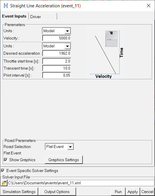
Figure 1.
- Event Parameters
-
Parameter Description Units Length unit selection (Model, m, ft). Acceleration unit selection (Model, m/s2, g’s).
Velocity Initial vehicle velocity. Desired acceleration Desired Acceleration rate of the vehicle. Throttle start time Time at which the vehicle acceleration starts. Transient time Time period for which the vehicle accelerates. Print interval Time interval of data output to the plot file (.plt) and graphics file (.h3d). - Road Parameters
- Use the road parameters to select the road that the vehicle drives on for the event.
You can choose to use a flat road, a road data file you select from the event editor,
or the road data files selected by tires. The table below describes the parameters in
detail.
Parameter Description Road Selection This option menu determines the road selected for the event. There are three choices: - Flat Road - Use a flat, smooth road for the event. No road file is needed. Use the road settings to control the road graphics and road mu.
- From Event - Select a road file from the event road file field. All tires in the model use this road file when running the event.
- From Tires - For each tire in the model, use the road file selected for that tire in the AutoTire panel. This allows you to use different road files for different tires.
Road Selection = Flat Road When the road Selection is Flat Road, then the event is run on automatically generated flat road data file.
Mu (Friction Scale) Enter a value greater than or equal to zero that scales the tire-road surface friction. Note the tire-road surface friction is defined in the tire properties. So, if you enter a 0.5 here and the tire-road friction coefficient is 0.8, the effective coefficient of friction is 0.5*0.8 = 0.4. Show Graphics Check this box to create graphics for the flat road. Note the graphics are created when you click the Apply or Run button on the event editor. Graphic Settings Push this button to display a dialog that controls the flat road graphics, to learn more about the controls see the Road Settings section below. Road Selection = From Event Road File When the Road Selection option is From Event, use the road file field to select the road file for the event. Road Selection = From AutoTires
When the Road Selection is From AutoTires, then each tire runs on the road property file specified for it in the AutoTire panel. This allows the use of different road files for different tires, for example, one road for the right tires and another for the left tires to provide different vertical disturbance.
Driver
Use the Driver tab to set Proportional, Integral and Derivative (PID) gains and output signal filtering. The PID controllers employed by the Driver depend on the vehicle.
PID Controllers
- Lean PID
- For leaning vehicles, the Lean PID takes as input a demand lean angle and outputs front fork (steering) angle. For open loop events the lean angle demand is a function of time. For closed loop path following events the demand lean angle is computed based on the vehicle speed and the path curvature with a correction for lateral path error. For more information see the Lean Angle Controller - Two-wheelers topic and also the Gain Tuning for Leaning Two and Three Wheeler Vehicles topic.
- Lateral Error PID
- For leaning vehicles, the Lateral Error PID takes as input the predicted lateral path error and outputs an increment to the demanded lean angle. The lateral error is computed by predicting the vehicle’s lateral position relative to the path by the look ahead time in the future. The Lateral Error PID acts to lean the vehicle toward the path. For more information see the Lean Angle Controller - Two-wheelers topic.
- Longitudinal PID
- You can add the longitudinal PID controller to any vehicle to correct for disturbances not accounted for in the feedforward section of the longitudinal controller and to remove steady-state error. The longitudinal PID takes as input velocity error and outputs throttle.
For more information see the Altair Driver Mathematical Methods topic.
Signal Settings
Use the signal settings to set minimum, maximum, and initial values for Steering, Throttle, Brake, Gear and Clutch signals output by the driver. The smoothing frequency is used to control how fast the Driver changes signals. Only closed loop control signals from the Driver are smoothed. Open loop signals are not smoothed.
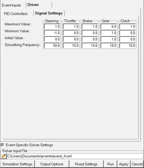
Figure 2.
Road Settings
The Road Settings dialog controls the display of the rectangular road graphics.
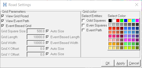
Figure 3. Road Setting Dialog
Grid Parameters
| Parameter | Description |
|---|---|
| View Grid Road | The View Grid Road check box toggles the road grid graphics on and off. |
| View Event Path | The View Event Path check box toggles the event path
graphics on and off. Note: This check box is disabled for open loop events without
a path.
|
| Event Based Grid | Check the Event Based Grid option to automatically size the length and width of the road graphics based on the event parameters, like the initial straight and radius for the constant radius event. Remove the check from the Event Based Grid option to input the size of the road graphics. |
| Grid Square Size | Enter a positive value in model units giving the length and width of squares in the road graphics. |
| Grid Length | Enter a positive value in model units giving the length of the road graphics. |
| Grid Width | Enter a positive value in model units giving the width of the road graphics. |
| Grid X Offset | Enter a value in model units giving the distance to offset the road graphics in the longitudinal direction. |
| Grid Y Offset | Enter a value in model units giving the distance to offset the road graphics in the lateral direction. |