Gain Tuning for Leaning Two and Three Wheeler Vehicles
Altair Driver controls the direction and lean angle of leaning vehicles by steering the front fork. Altair Driver counter steers initially to create an unbalanced moment about the vehicle’s longitudinal axis to start the vehicle leaning in the demanded direction and then steers to control the vehicle’s lean angle match a demanded lean angle. For open loop events like step-steer and sinusoidal steer, the demanded lean angle is a function of time and the output of the event is the vehicle’s path. For closed loop path following events, like constant radius cornering or road course drive, the demanded lean angle is the sum of a target lean angle and corrective lean angle. The target lean angle depends on the vehicle speed, the path curvature, and the vehicle mass and the angular momentum wheels and tires. The target lean angle balances the moments on the vehicle due to gravity, lateral acceleration, and the change in angular momentum of the wheel and tires. While the corrective lean angle is meant to minimize the path error at the look-a head-time in the future. For more information see the Leaning Two and Three Wheeler Vehicles topic.
Please note, however, that if the vehicle speed drops too low, steering the front fork is ineffective because neither the tire force nor the change in direction of angular momentum of the wheels and tires produce a moment on the vehicle large enough to overcome the moment on the vehicle due to gravity and the vehicle capsizes. One set of controller gains may allow Altair Driver to control the vehicle to a lower speed than another set all else being equal, but given that leaning vehicles are inherently un-stable at low speeds capsizing at low speed cannot be eliminated by tuning the gains.
For both open loop and closed loop events Altair Driver employs a PID controller of type ‘Follow_Lean’ in the Altair Driver File (.adf). The input to the ‘Follow_Lean’ is the error between the demanded lean angle and actual lean angle. The ‘Follow_Lean’ controller’s output is the front fork steer angle. For open loop events the demanded lean angle is an explicit function of time. For path following events the demanded lean angle comes implicitly from the feed-forward steer controller that references the ‘Follow_Lean’ controller.
[PID_CONTROLLER]
TAG = 'PID'
TYPE = 'FOLLOW_LEAN'
KP = 20
KI = 30
KD = 7 Figure 1.
 Now you can iterate to tune the gains to meet your needs. A method for tuning the gains to achieve good performance in a constant radius cornering event is described below.
How to Tune a 'FOLLOW-LEAN' PID Controller
- Initially, set the integral (
 ) and derivative (
 ) gains to zero, then increase proportional (
 ) gain until the vehicle shows an oscillating behavior.
 - Increase the gain until oscillations stop.
- Repeat the two steps above until increasing the gain does not stop the oscillations.
- Increase the gain until it brings the system to the setpoint with the
desired/lesser number of oscillations, but a quicker response.
| Parameter | Rise Time | Overshoot | Setting Time |
|---|---|---|---|
|
Decrease | Increase | Small change |
|
Decrease | Increase | Increase |
|
Minor change | Decrease | Decrease |
Example Constant Radius Cornering (CRC) Event
For a default wizard-built motorcycle model and Constant Radius Cornering (CRC) event, the gain values of the ‘FOLLOW_LEAN’ PID controller are tuned step by step to achieve good steering performance. The controller performance may be seen by plotting the REQSUB “steer control feedback” output request channels f2 (demand lean angle) and f3 (actual lean angle) from either the .plt, .mrf, or .abf output files in HyperGraph.
- Step 1: Set Integral and Derivative Gains to Zero
-
Edit the constant radius cornering .adf file and set the ‘FOLLOW_LEAN’ proportional () gain to 10 and the integral () and derivative () gains to zero (0).
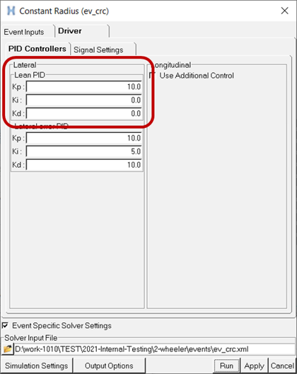
Figure 2.Run the constant radius event and plot actual lean angle and/or animate the results in HyperView. Observe that motorcycle capsizes ( |lean angle| >> 45 degrees) as shown in the plot below:
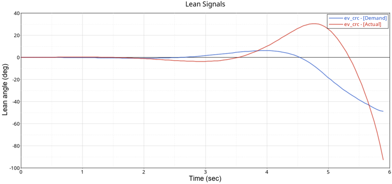
Figure 3. Motorcycle Capsizes for Lean Control Gains Kp = 10, Ki = 0, Kd = 0 - Step 2: Increase Proportional Gain
-
Edit the lean control gains from the Constant Radius event editor: keep the integral and derivative gains to zero and increase the proportional gain from ten (10) to thirty (30) as shown below:
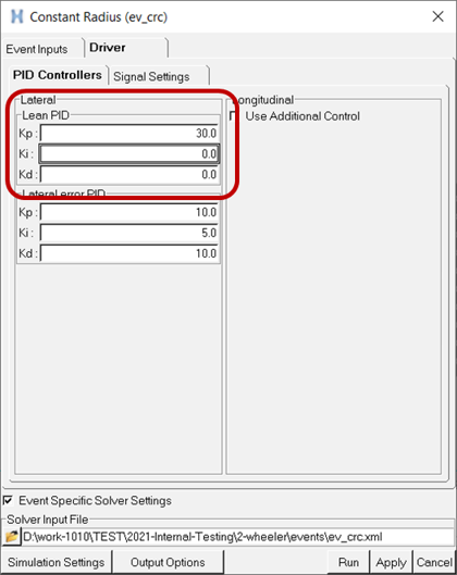
Rerun the Constant Radius Cornering event with the new Kp = 30, plot the actual lean angle or animate the results in HyperView. At higher speed and lateral acceleration, the motorcycle becomes unstable and capsizes.
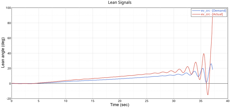
Figure 4. Motorcycle Unstable at High Speed for Lean Control Gains Kp = 30, Ki = 0, Kd = 0 - Step 3: Increase Derivative Gain
-
Edit the lean control gains from the Constant Radius event editor and introduce a derivative gain of ten (10) as show, while leaving the proportional gain unchanged:
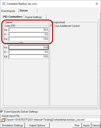
Figure 5.Rerun the Constant Radius Cornering event, and plot the actual lean angle and demanded lean angle in HyperView. Observe that the motorcycle does not capsize, but the error between the actual and demanded lean angle is large.
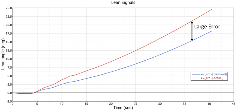
Figure 6. Motorcycle Large Error for Lean Control Gains Kp = 30, Ki = 0, Kd = 10 - Step 4: Increase Integral Gain
-
Edit the lean control gains from the Constant Radius event editor and set the integral gain of twenty (20), while leaving the proportional and derivative gains unchanged:
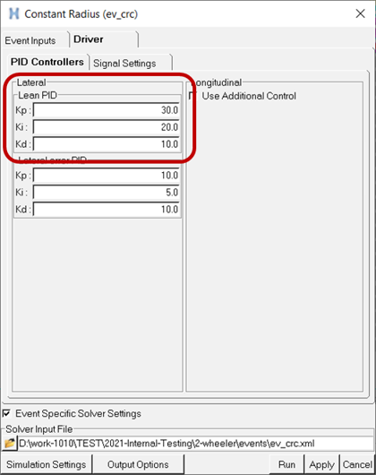
Figure 7.Rerun the Constant Radius Cornering event, and again, plot the actual lean angle and demanded lean angle in HyperView. Observe that the motorcycle does not capsize and the error between the actual and demand lean angle is small:
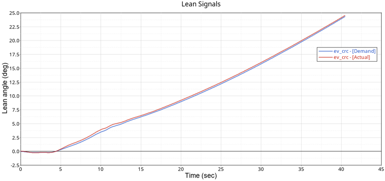
Figure 8. Small Error with Tuned Error Lean Control Gains: Kp = 30, Ki = 20, Kd = 10