The disk brake system is designed to simulate braking effects on the heavy vehicles
using disk brakes. The disk brake system is further divided into front and rear
brake disk systems. The front or rear brake disk systems apply a torque on the wheel
joint to oppose the wheel motion. The braking torque is calculated using driver
brake demand and user defined parameters such as disk brake radius, coefficient of
friction, master cylinder bore diameter, pedal ratio, etc.
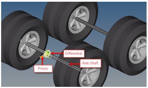
Single-axle Driveline
In the single-axle driveline system, the differential is mounted on the rear-front
axle is located in the transaxle parallel to the transmission. As the power is
applied, the differential distributes it to the front wheels. Figure 1.
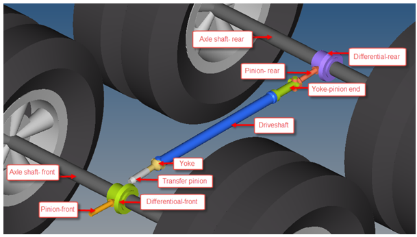
Two-axle Driveline
The difference is that the two axle driveline has a driveshaft system extending from
the transmission in front to the differential in the rear. The driveshaft connects
via a yoke to allow for vertical and longitudinal suspension movement. The main body
parts included in the two axle driveline is shown in the following image. Figure 2.
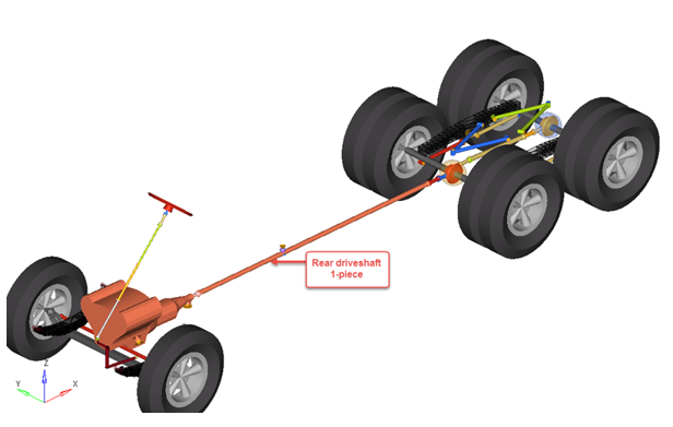
Rear Driveshaft 1-piece
A single piece driveshaft extending from the transmission in the front to the
differential in the rear via a yoke-pinion end. The driveshaft connects via a yoke
in the front to allow for vertical and longitudinal suspension movement. Figure 3.
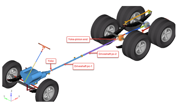
Rear Driveshaft 2-piece
A two piece driveshaft extending from the transmission in front to the differential
in the rear via a yoke-pinion end. The driveshaft connects via a yoke in the front
to allow for vertical and longitudinal suspension movement. Figure 4.
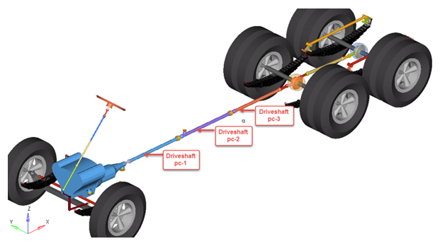
Rear Driveshaft 3-piece
A three piece driveshaft extending from the transmission in front to the differential
in the rear via a yoke-pinion end. The driveshaft connects via a yoke in the front
to allow for vertical and longitudinal suspension movement. Figure 5.