Create E-Lines
Use Create E-Lines tool to create evaluation lines at component interfaces.
- Fast Create
- Use to create many E-Lines at a time to get quick and approximate overview of squeak and rattle risk zones.
- Manual Create
- Use to manually create one E-Line at a time and control the setup to ensure the accuracy in analysis results.
Fast Create
-
From Setup group, select Create
E-Line tool.
 Figure 1. A guide bar will appear.
 -
Optional: Click
 to open edit E-line
definition parameters under Options menu.
to open edit E-line
definition parameters under Options menu.
-
Click
 .
This creates the E-Lines at the interfaces of the selected components along the geometric lines.
.
This creates the E-Lines at the interfaces of the selected components along the geometric lines.
Manual Create
-
From Setup group, select Create
E-Line tool.
Figure 2. A guide bar will appear.
-
Deactivate
 to open Manual mode.

-
Optional: Click to open edit E-line definition parameters under
Options menu.
-
Click
This creates the E-Lines at the interfaces of the selected components along the geometric lines.Tip:
- All E-lines can be edited at a later stage (see Manage and Review E-lines). For a potential process speed-up, you can create all lines in fast mode and edit them later.
- To create a Single Point E-line, select an element as master and another as slave. This is used to create flexible attachments such as clips/snaps and diagonal E-lines to track opening distortion.
Create E-Lines Options
Spacing: Value for the spacing between two adjacent Evaluation Points on an E-Line
Search Distance: Value for search / gap tolerance between the selected master-slave component
Gap Direction: Realization Projection direction, controls creation of the local coordinate systems which determines the Gap Direction
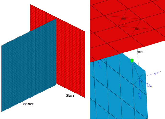 Figure 3.
 Zdirection will be perpendicular or Normal to Master component.
In Plane to Master
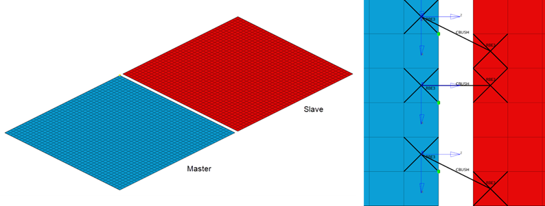 Figure 4.
 Z direction will be In Plane to Master component.
Contact Types: Defined Contact type for this E-Line, this is based on Youngs' modulus value of the Master and Slave FE Material.