Campbell Diagram
In rotordynamical systems, the eigenfrequencies often depend on the rotation rates due to the induced gyroscopic effects or variable hydrodynamic conditions in fluid bearings. You can use a Campbell Diagram to illustrate this.
-
From the Options panel, verify that
Enable Unit Scaling is checked:
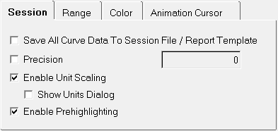
Figure 1. -
Return to the Build Plots panel and make selections similar to those shown in
the following image and click Apply.
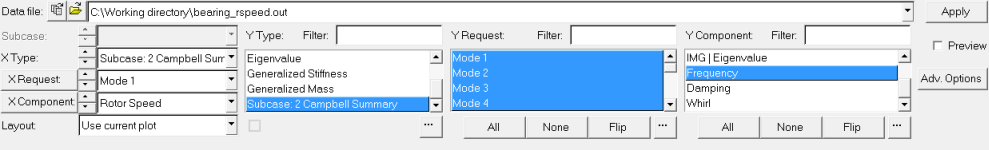
Figure 2.A plot similar to this is displayed:
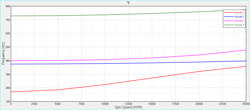
Figure 3. -
From the Plot Browser, select all modes, right-click, and
select .
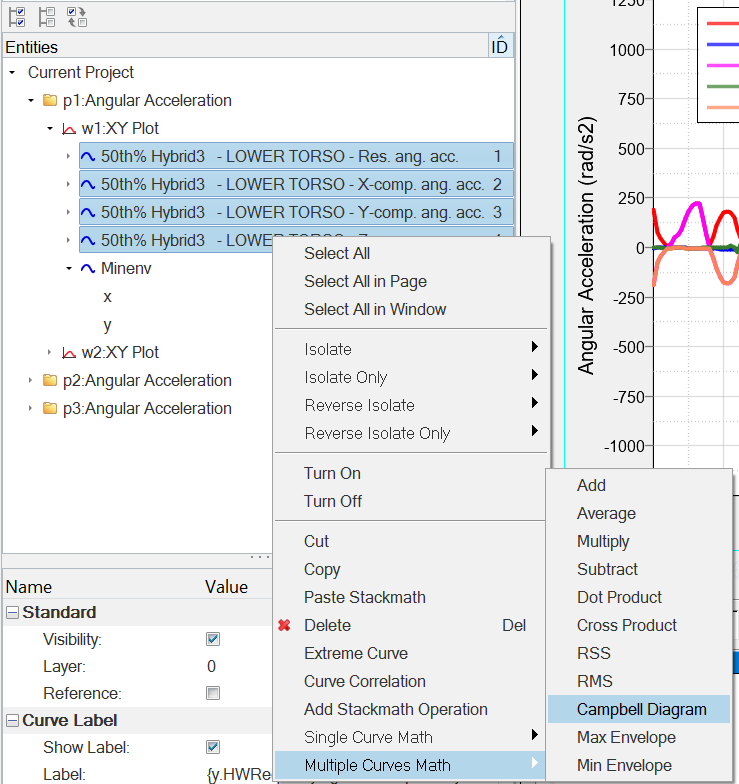
Figure 4.The following dialog is displayed: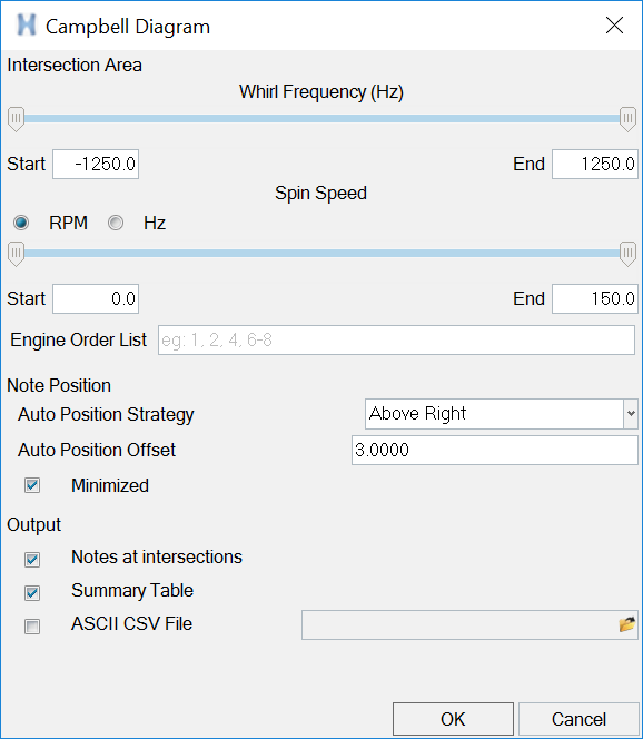
Figure 5. -
Under Note Position, defaults are set to position the notes Above Right, with
an offset or 3.0000, and the notes will be minimized to display the blue icon
instead of the note text,
 .
.
-
Click OK after you've made your selections.
The Campbell Diagram plot and the summary table are displayed. The summary table on the right displays the information for the modes you selected to display in the plot. The colors used correspond to the mode colors in the plot.
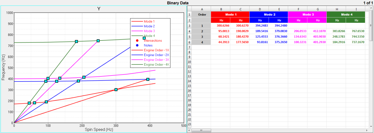
Figure 6.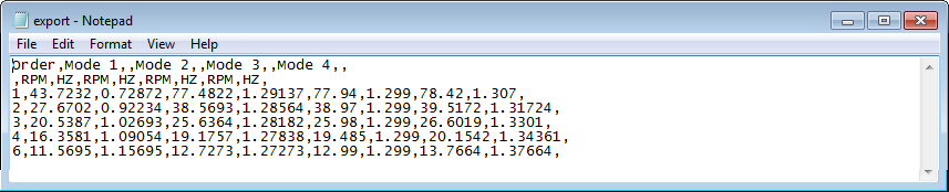
Figure 7. CSV file example: -
All of the intersections are created and you can hover over the minimized notes
to display the information for each.
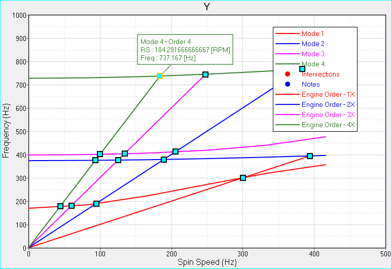
Figure 8. -
If you use RPM as the units for the x-axis, and then enter 1-4 in the Engine
Order List field in the Campbell Diagram dialog, your results would look similar
to this:
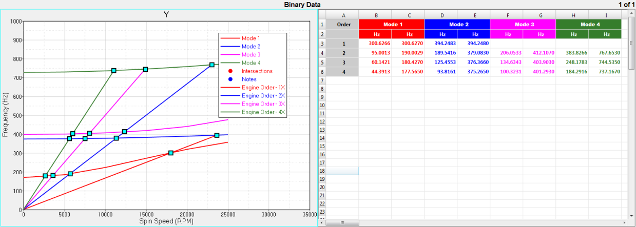
Figure 9. -
If you do not select Enable Unit Scaling from the Options panel, when you
select Campbell Diagram from the Multiple Curves Math menu, the following
message is displayed:
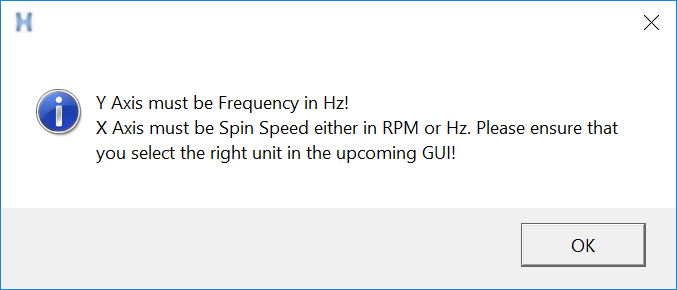
Figure 10.You must resolve the unit discrepancy in the the Campbell Diagram, as shown in the red box below. Note that this does not appear when you enable unit scaling.
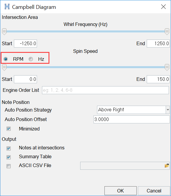
Figure 11.