Configure a Cam Die
Designate a part or surface(s) on your model for the cam die.
-
Add a cam die to an operation, then select the Cam
Die.

-
Define the stroke, velocity, and Coulomb friction coefficient.
-
In the microdialog, to set the stroke value to the closed position of
the tools, select
 . To specify a value, select the pencil tool
 , type in a value, and press Enter.
Note: If you define the stroke value to be larger than the auto-calculated or closed position, the open position of the tool automatically repositions to match the stroke value to prevent a collision with the bottom die.
, type in a value, and press Enter.
Note: If you define the stroke value to be larger than the auto-calculated or closed position, the open position of the tool automatically repositions to match the stroke value to prevent a collision with the bottom die. -
To define the Coulomb friction coefficient, in the microdialog, enter a
value next to the icon
 .
.
-
In the microdialog, to set the stroke value to the closed position of
the tools, select
-
Click to confirm the configuration of the cam die.
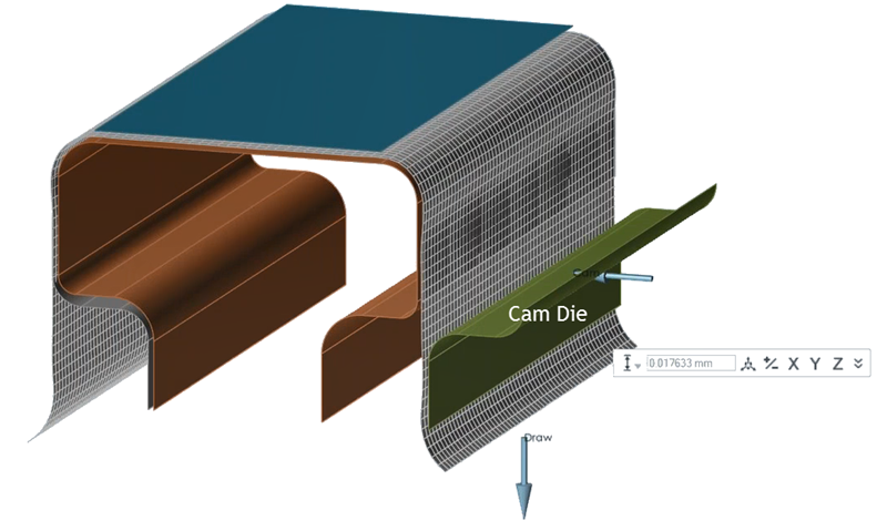
Figure 1. Crash Form Operation with a Cam Die
Keyboard Shortcuts & Mouse Controls
| To | Do this |
|---|---|
| Add/remove from selection | Ctrl+click |
| Reverse selection | Ctrl+R |