Creating a Cable Shield Layer (Shield Properties)

Create a cable shield by defining the frequency-dependent surface impedance, transfer impedance and transfer admittance matrix.

  1. On the Cables tab, in the Definitions group, click the  Cable shield icon.
  2. Under Shield layer(s), click Single to create a single-layered shield.
  3. On the Inner layer tab, on the Impedance definition tab, in the Definition method drop-down list, select Define properties.


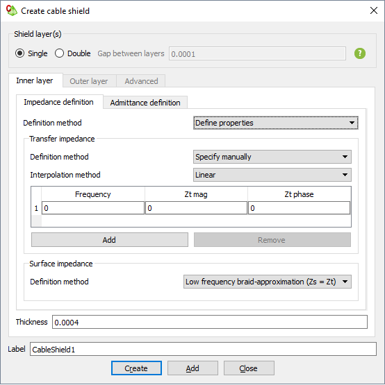
    Figure 1. The Create cable shield dialog.
  4. Under Transfer impedance, from the Definition method drop-down list, select one of the following:
    • To define the properties manually, select Specify manually.
      • In the Frequency column, specify the frequency at which the transfer impedance and admittance are specified.
      • In the Zt mag column, specify the magnitude of the transfer impedance.
      • In the Zt phase column, specify the phase of the transfer impedance.
    • To define the properties from an XML file, select Load from file.
      • In the Filename field, browse to the file location.
  5. Under Transfer impedance, in the Interpolation method drop-down list, select one of the following:
    • To use the default interpolation method between the data points, select Default.
    • To use a linear interpolation method between the data points, select Linear.
    • To use a cubic spline interpolation method between the data points, select Cubic spline.
    • To use a rational (Thiele) interpolation method between the data points, select Rational.
    • To use a constant interpolation method between the data points, select Constant.
  6. Under Surface impedance, from the Definition method drop-down list, select one of the following:
    • To define the surface impedance (Zs) equal to the transfer impedance (Zt), select Low frequency braid-approximation (Zs = Zt).
    • To define the properties manually, select Specify manually.
      • In the Frequency column, specify the frequencies at which the surface impedance are specified.
      • In the Zs mag column, specify the magnitude of the surface impedance for each frequency.
      • In the Zs phase column, specify the phase of the surface impedance for each frequency.
    • To define the properties from an XML file, select Load from file.
      • In the Filename field, browse to the file location.
    • To define the properties from a metallic material, select Solid (metallic material)
      • In the Shield metal drop-down list, select one of the following:
        • To create a PEC shield, select Perfect electric conductor.
        • To create a shield consisting of a predefined metal, select the metal.
        • To create a shield consisting of a metal, which is not yet defined in the model, click the icon to define a metal or add a metal from the media library.
  7. On the Inner layer tab, on the Admittance definition tab, in the Definition method drop-down list, select Define properties.


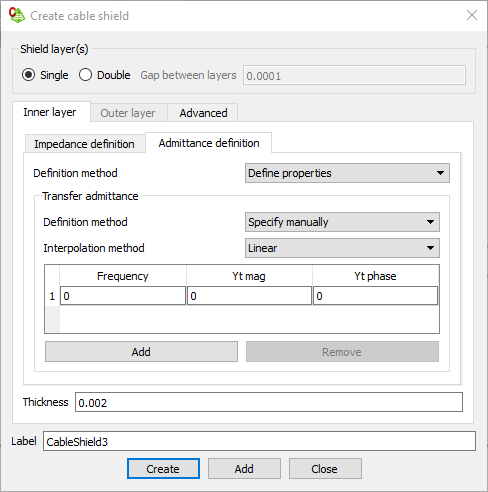
    Figure 2. The Create cable shield dialog.
  8. Under Transfer admittance, from the Definition method drop-down list, select one of the following:
    • To define the properties manually, select Specify manually.
      • In the Frequency column, specify the frequencies at which the transfer impedance and admittance are specified.
      • In the Yt mag column, specify the magnitude of the transfer admittance for each frequency.
      • In the Yt phase column, specify the phase of the transfer admittance for each frequency.
    • To define the properties from an XML file, select Load from file.
      • In the Filename field, browse to the file location.
  9. Under Transfer impedance, from the Interpolation method drop-down list, select one of the following:
    • To use the default interpolation method between the data points, select Default.
    • To use a linear interpolation method between the data points, select Linear.
    • To use a cubic spline interpolation method between the data points, select Cubic spline.
    • To use a rational (Thiele) interpolation method between the data points, select Rational.
    • To use a constant interpolation method between the data points, select Constant.
  10. On the Inner layer tab, from the Thickness field, enter a value for the thickness of the shield.
  11. In the Label field, add a unique label for the cable shield.
  12. Click Create to create the cable shield and close the dialog.