Creating a Braided Cable Shield Layer (Vance, Tyni or Demoulin)
Create a single layer, braided (Vance, Tyni, Demoulin) cable shield. For a braided shield layer, the relevant braid parameters and weave metal are specified and the Solver determines the frequency-dependent impedance (Zs + Zt) and admittance (Yt) matrix using the Vance, Tyni or Demoulin formulation.
-
On the Cables tab, in the
Definitions group, click the
 Cable shield icon.
-
On the Inner layer tab, on the Impedance
definition tab, from the Definition
method
drop-down list, select one of the following:
- Braided (Vance)
- Braided (Tyni)
- Braided (Demoulin)
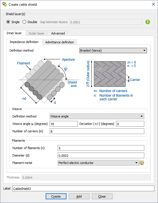
Figure 1. The Create cable shield dialog. -
Under Filaments, specify the following:
-
In the Filament metal
drop-down list, select one of the following:
- To create a filament consisting of PEC, select Perfect electric conductor.
- To create a filament consisting of a predefined metal, select the metal.
- To create a filament consisting of a metal, which is not yet
defined in the model, select the
 icon to define a metal or add a metal from the media
library.
icon to define a metal or add a metal from the media
library.
-
In the Filament metal
drop-down list, select one of the following:
Note: The Thickness of a Vance,
Tyni and Demoulin
shield layer is two times the filament diameter (d).
-
On the Inner layer tab, on the Admittance
definition tab, select Same as impedance
definition, from the Definition method
drop-down list to use the Vance, Tynior Demoulin formulation for the admittance matrix.
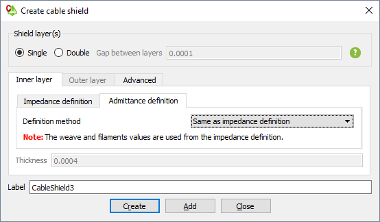
Figure 2. The Create cable shield dialog.Note:The weave and filaments values are used from the impedance definition to calculate the admittance matrix.