Altair Manufacturing Solver 2021.2 Release Notes
General
Altair Manufacturing Solver (AMS) is a state-of-the-art solver suite for manufacturing applications built on a parallel, modular, and extensible framework that is suitable for simulations of manufacturing processes. The current version of Manufacturing Solver includes casting, molding, and welding solution modules.
Highlights
- AMS has a new solver for additive manufacturing with a user interface in Inspire - Print3D.
- AMS has a new solver for welding with the user interface in SimLab.
- Casting solver now has the much-awaited thermomechanical module with contact modeling.
- Molding solver now has enabled parallel solutions for filling and cooling analysis with and without mold.
Additive Manufacturing (3DP for SLM)
The AMS Additive Manufacturing (3DP) solution module is aimed at modeling the metal additive manufacturing process based on laser powder bed technology. The solver is based on implicit finite element methods. It is capable of predicting transient temperature history as the part is being printed. It also includes an inherent strain-based mechanical solver which is designed to provide a fast and accurate prediction of part distortion and springback results as well as residual stress.
New Features
- A New Fast Inherent Strain Solver
- This version includes a new inherent strain solver to simulate the deformation of the 3D printed parts. This solver uses an inherent strain tensor as input which depends on the material and printing process information. For this reason, the inherent strain tensor should be calibrated with a measured deformation of a printed part.
- New Fast Thermal Solver
- AMS 3DP module has implemented a new thermal solver using a coarse tetrahedral mesh. This mesh is larger than the actual printing layer. The solver uses a level set to locally refine the mesh to compute accurate results for the given coarse mesh. This solver predicts the temperature distribution during the printing process at the macro level.
Metal Casting
New Features
- Thermomechanical Stress Analysis during Solidification
- This feature in the casting solver will predict the warpage and compute
the residual stresses during the solidification of the part while it is
still inside the mold. This is achieved through the implementation of a
new solution module to perform nonlinear stress analysis. This module
supports an elasto-viscoplastic material constitutive law to model the
material behavior. The contact condition between the mold and cast part
is implemented using the augmented Lagrange multipliers method.
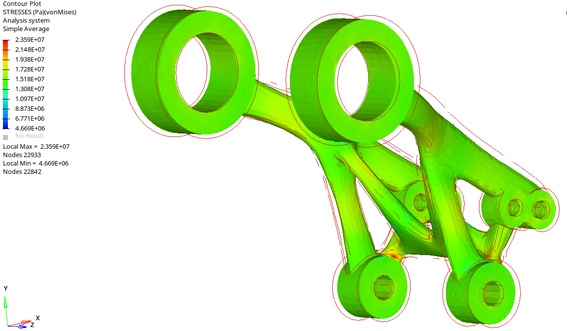
Figure 1.
Enhancements
- Open/Close Inlets as Function of Time
- This feature allows the inlets to be opened and closed as a function of
time. The feature has two key applications:
- It helps to model imbalances in the running system without modeling the whole runner system.
- Model filling of the hot chamber with different inlets that open and close at different times.
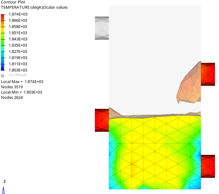
Figure 2. - Parallel MPI Version of Linux Solver
- A parallel MPI version of the solver was made available in the previous release. This version significantly improves efficiency in shared-memory machines.
Resolved Issues
- Cooling channels were not restarted every cycle
- In the previous version, cooling channels were only being activated at
the beginning of the first cycle. This issue is resolved and now they
are restarted at the beginning of every cycle. In the image below, you
can see how in the previous version the cooling channel was only
activated in the first cycle (blue line), while in the new version you
can see the cooling effect in every cycle (red line).
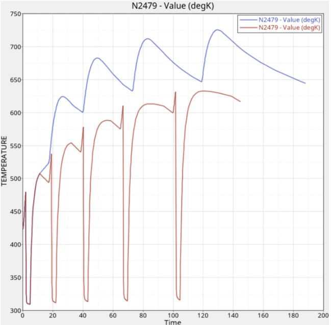
Figure 3. - Mold boundary conditions for mold after shakeout were not correct
- In a multi-cycle analysis, boundary conditions applied to the mold were
not correct after each shakeout. This led to underestimating the cooling
effect when the mold is open. This issue is now resolved. In the image
below, you can see the temperature evolution of a mold node. The red
line shows temperature evaluation after this issue was resolved and the
blue line shows the result with the incorrect BC. This clearly shows the
cooling effect when the mold is open.
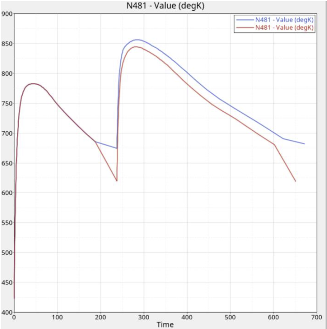
Figure 4.
Injection Molding
Enhancements
- Export OptiStruct data deck in Large Field Fixed Format
- The molding solver exports a FEM data deck for FSI and warpage analysis that can be readily solved using OptiStruct. The solver was exporting in a valid comma-separated format, however, this format was not supported in some of the pre-processors. To overcome this limitation, the solver is now enhanced to export the fem input deck for OptiStruct in the large field fixed format. This deck can be solved directly or imported into the SimLab user profile to set up additional analysis parameters and run the structural analysis using OptiStruct solver.
- Synchronize and Control Inlets with a Valve Controller
- This feature allows you to synchronize an inlet with a valve controller. This feature enables you to define several gates of a hot runner system without modeling the complete runner system. When a complete hot runner system is modeled, the valve controllers automatically handle the injection of the polymers by keeping at least one injection path open from the main inlet from the extruder to the part. This is not the case when only the gates and some portion of the hot runner system are modeled. In such cases, you can define multiple injection BCs and synchronize these inlets with the corresponding valve controllers to switch them on/off, to get a specific sequence. If an inlet is associated with a valve, then zero velocity is prescribed to this inlet when the valve is closed, and normal velocity is applied if the valve is opened. This enables you to control injection correctly even when only a part of the runner system is modeled.
- Injection BC Controllers
- This enhancement is an extension of valve controllers to control
injection BC, even in a cold runner system. The controllers set the
state of the inlet. When its state is zero, then the inlet is closed and
zero velocity is applied. When its state is one, then the inlet uses the
velocity as specified in the BC. You can control the injection BC using
many different control options. These include:
- Flow front position
- Pressure at some specific nodes
- Percentage filled volume of the cavity
- Other solution variables
- Parallel MPI Version of Linux Solver
- A parallel MPI version of the solver was made available in the previous release. This version significantly improves efficiency in shared-memory machines. This feature is available to most solver modules, but not all. For example, the molding solver is enabled to perform fill analysis with mold and cool analysis with/without mold in a parallel computing environment. However, this feature is not available for packing or fiber orientation modules.
- New Result: Weld Surface Angle
- When two separated polymer melt fronts recombine/join, weld lines are formed. The strength of the part at these weld lines depend on the angle at which melt fronts meet. For this reason, it is important to know the weld line meeting angle. The molding solver determines the weld by determining the angle of the tangents on the two meeting fronts. It considers this a weld surface only if the angle is less than 135 degrees. An angle of zero degrees indicates the fronts are colliding head-on and above 135 degrees they begin to meet tangentially.
- New Result: Part Thickness
- Local part thickness plays a critical role in both the part design and the process design. For example, it is used in determining the gate locations, it controls how well the part cools locally, and also the part warpage. In this release, this result is available for post-processing.
- New Result: Frozen Layer
- When the temperature of nodes goes below the no-flow temperature, these nodes are marked as frozen. This is now available as a new result for post-processing.
- Frozen Volume Percentage in CSV file
- When the temperature of nodes goes below the no-flow temperature, these nodes are marked as frozen. This data is used to calculate the percentage of frozen material to determine the time at which the parts can be ejected from the mold.
- Result Names in H3D file
- Result names in the H3D file included the corresponding units of each result. Since both Inspire and SimLab are now unit-enabled, you can post-process the results in a variety of unit systems. Hence, hard-coding the result units will lead to confusion and it is removed in this release. If you conduct post-processing in HV, you should assume that SI units are used.
Resolved Issues
- Export Fiber Orientation Tensor XML file
- The molding solver required extra data specification to export this file, even though it is needed whenever fiber orientation analysis is performed. Now the solver will write fiber orientation tensor data in an XML file whenever the fiber orientation analysis is performed.
- Hot Runners and Stopping Cooling Simulation
- When the model includes a hot runner system, the temperature in these hot runners is maintained at the inlet melt temperature and they will never cool. The stop criteria of cooling simulation should exclude these regions and also the regions near the valve while checking if the temperature is below the ejection temperature. This issue is now resolved and the solver considers these while evaluating the stop criteria.
Welding
- Thermal Analysis
- The AMS Welding solver supports transient thermal analysis of the welding process with temperature-dependent material properties such as conductivity and specific heat. It takes into account the melting and solidification of metals due to the heating and cooling cycles, therefore is able to predict the size of the melt pool and heat-affected zone (HAZ). A set of standard volumetric heat sources are supported, for example: double-ellipsoid and spherical heat sources. Peak temperature and cooling rate results are captured during the welding simulation.
- Fast Distortion Analysis
- The fast distortion analysis supports fast distortion prediction utilizing an inherent strain-based solution method. It gives quick distortion predictions using linear elastic structural analysis with user-given inherent strain data. The solver also supports the modeling of various filler material deposition sequences to help predict and mitigate overall weld distortion.
- Coupled Analysis
- The AMS Welding solver supports coupled thermal-mechanical analysis to predict distortion and residual stress induced by temperature gradient during the welding process. The solver supports temperature-dependent thermal material properties and linear thermo-elastic constitutive models.
New Features
- Supported Welding Processes
- Arc welding
- Supported Physics
- Transient energy balance equation: heating and cooling of the weldments and workpiece.
- Supported Results
- Thermal Analysis
- Temperature
- Heat Flux
- Peak Temperature
- Cooling Rate