Spot Welds
Spot welds connect surface parts together by welding them at specific locations. You can apply spot welds at any location on a surface part or at any existing point.
Click the satellite icon ![]() that
appears when you hover over the Spot Welds tool to view a list of all spot welds in your
model.
that
appears when you hover over the Spot Welds tool to view a list of all spot welds in your
model.
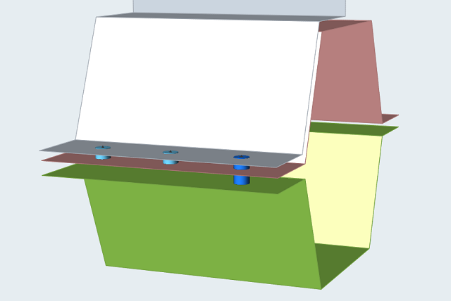 Figure 1. Spot Weld Example. Spot welds created at imprinted points on the model
Creating Spot Welds
Select the tool, then click on the model to create a spot weld.
-
On the Structures ribbon, select the Spot Welds
tool.

- Select weld locations. Click any location on a surface part, or select an imprinted point or a point in space.
- Optional:
Click Parts on the guide bar, then click on a surface
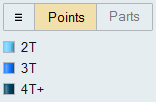
part to add or remove it from any selected spot welds. The legend indicates how
many surfaces are included in the weld.
- Right-click and mouse through the check mark to exit, or double-right-click.
- If Parts is selected on the guide bar and there are no spot welds selected, when you select a part, it will remove the part from all spot welds in the model.
- Spot welds can be organized into groups using the Spot Welds table or the Model Browser. Once created, you can move them between groups, but each spot weld can only be in one group.
- If you create a part that contains only points, then select this part in the Model Browser with the Spot Welds tool open; it will create spot welds at all of the points.
Microdialog Options
Use the options in the microdialog to modify the spot weld once it is created.
- Move Weld: Move the selected spot welds using the Move tool. This only works on planar geometry.
- Weld Diameter: Enter a diameter in the text box. Applies to all selected spot welds.
Search Distance
The search distance determines which surface parts will be included in the spot weld.
Click the Find Options
 menu on the guide bar to change the Search Distance.

The starting point for the search distance is the selected point or location where the spot weld was created. For points at a distance, the point projected onto the nearest surface part is used as the starting location.
Spot Welds Table
The Spot Welds table lists all of the spot welds in your model and can be used to change the weld diameter and assigned material.
You can also use the table to create and organize spots welds into weld groups. Click
the ![]() satellite icon on the Spot Welds tool to display the
table.
satellite icon on the Spot Welds tool to display the
table.
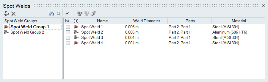
Figure 2. Spot Welds Table
The table data can be edited with the following actions:
| To | Do this |
|---|---|
| Rename a spot weld | Select the cell in the table and then click again to make the field editable. |
| Change the material | Select the cell in the table and then select a different option from the list. |
| Sort a column | Click the column header. Click repeatedly to toggle between ascending and descending order. |
| Add or remove columns | Right-click on a column header. |
| Create a spot weld group | Click the  icon. icon. |
| Move a spot weld to a different group | Select the check box next to the spot weld, then right-click and select Move to... from the context menu. |
Mouse Controls and Keyboard Shortcuts
| To | Do this |
|---|---|
| Select multiple points | Hold down the Ctrl key and left-click, or use box selection to create welds at all selected points. |
| Select surface parts to include | Hold down the Ctrl key and left-click a surface part to add it to or remove it from the spot weld. |
| Deselect all spot welds | Left-click on an empty space in the modeling window. |
| Delete a spot weld | Select a spot weld and press Delete. |
| Exit the tool | Right-click and mouse through the check mark to exit, or double-right-click. |