Systems
Use the Systems tool to create and apply user-defined coordinate systems to loads, supports, and displacements.
This is useful for aligning loads to a local coordinate system rather than the global coordinate system. Keep in mind that results are only shown in the global coordinate system.
In addition, systems can be manually defined in a .csv file and imported using the Load Cases table. They will also be imported as part of the geometry when opening a Catia, JT, ProE, Step, or NX file.
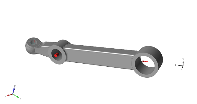
Figure 1. A two force member with a user-defined coordinate system.
Create a Local System
Create a local coordinate system and apply it to a load such as a force or support.
-
On the Structures ribbon, click the Systems tool.

-
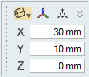
To translate or rotate the system:
- Click the Move tool.

- Enter the x, y, and z coordinates (translate).
- Enter the θx, θy, θz values (rotate).
- Click the Move tool.
- You can create cylindrical coordinate systems from the Systems tool
microdialog.
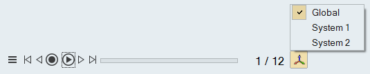
- Displacement components can be reviewed in local systems using the Animation
toolbar.
Apply a Local System to a Load
Use the microdialog for forces, supports, and displacements to apply a local coordinate system to a load.
- Double-click the force, support, or displacement in the modeling window.
-
Click the Global icon.
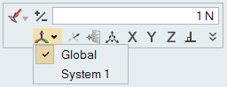
- Click a local system from the menu.
Import Systems Using the Load Cases Table
Use the Load Cases table to import loads, point parts, and/or systems from a .csv file.
- Open the Load Table Import.csv file in the Tutorials folder in the installation directory.
- Edit the file as needed to define your loads, point parts, or local coordinate systems.
-
Open the Load Cases table by clicking the
 satellite icon that appears when you hover over the
Loads, Disps, Accels, or Temps icon.
satellite icon that appears when you hover over the
Loads, Disps, Accels, or Temps icon.
-
Click the
 icon to import loads.