Forces
A force is a push or a pull in a particular direction on a part, and is a type of load. Use the Apply Force tool on the Loads icon to apply a force.
Forces can be applied to a point, edge, face, or hole center. Once applied, distributed forces on certain types of features can be converted to bearing forces or traction forces.
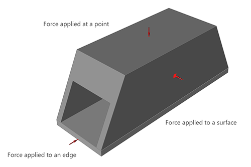
Figure 1. Forces Applied to a Point, Edge, or Face
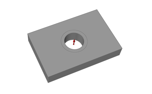
Figure 2. Forces Applied to a Hole Center
Apply a Force
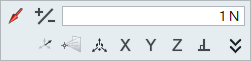
Select the Force tool, click on a feature, and enter a magnitude.
-
On the Structures ribbon, select the Force tool on the
Loads icon.

-
Enter the magnitude of the force in the text field of the microdialog and press
Enter.
-
Click the
 icon to reverse the direction of the force.
-
Use the options on the microdialog to change the
alignment of the force, using one of the following methods:
- Click the
 icon to orient the force to a local
system.
icon to orient the force to a local
system. - Select either direction force mode
 or
component force mode
or
component force mode  , then click the
  to define a
direction or component vectors.
to define a
direction or component vectors. - Use the X, Y, Z buttons to align the force to the X, Y, or Z axis. Click a second time to reverse the direction.
- Use the Move tool on the microdialog.
- Click the
- When created, forces are automatically assigned to the current load case.
- A distributed force acts in a single direction across the extent of an edge or face. You can change whether a force is distributed or not in the Property Editor.
- To apply a force that is perpendicular to a face at each point across its entire extent, like air pressure in a balloon, use a pressure instead of a force. You can also apply a force as a pressure if all you know is the magnitude of the force. Simply create a pressure and enter the magnitude in force units.
- Use the Property Editor to change the name, magnitude, mode, direction, and appearance of the force, and whether it rotates with the part.
Bearing Forces
A bearing force applied to a hole mimics the contact force between a shaft and a bushing.
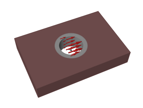
Figure 3. Bearing Force Applied to a Hole Center
Click ![]() on
the microdialog to convert a distributed force to a bearing force.
on
the microdialog to convert a distributed force to a bearing force.
Traction Forces
A traction force can be applied to a cylindrical face, and acts tangential to that face. This mimics contact forces between parts, such as friction.
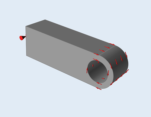
Figure 4. Traction Force Applied to a Cylindrical Face
Click ![]() on
the microdialog to convert a distributed force to a traction force.
on
the microdialog to convert a distributed force to a traction force.
Microdialog Options
Double-click a force arrow to enter editing mode, which opens the Force microdialog.
| Convert to a distributed, bearing, or traction force. | |
|
|
Change the direction of the force. |
 |
Enter a magnitude for the force. |
| Click the icon to orient the force to a local system. | |
|
|
Click the icon to switch between direction force mode and component force mode. |
|
|
Click the icon to enter/exit Multi-Selection mode. In this mode, you can click a feature to add/remove it from the selection. Outside of this mode, you need to hold down Ctrl while clicking. |
|
|
Translate or rotate the force using the Move tool. Use to place a force at a distance. |
|
|
Align the force to the x-, y-, or z-axis. |
|
|
Align the force normal (perpendicular) to the face. |
|
|
Align the force to the centerline of a hole. (This button only appears if the force is applied to the center of a cylindrical hole.) |
|
|
Click the chevron to orient the force by entering either a direction and magnitude (X, Y, and Z) or components (Fx, Fy, Fz). |
Mouse Controls and Keyboard Shortcuts
| Ctrl | Apply the force to multiple features on the same part. |
| Shift | Create a concentrated force at a point on an edge, face, or hole. |
| Right-click and mouse through the check mark to exit, or double-right-click. | Exit the tool. |