Turbulent Flow Through a 180 Degree Curved Channel
In this application, AcuSolve is used to simulate turbulent flow through a strongly curved two dimensional 180 degree U-duct channel. AcuSolve results are compared with experimental results adapted from Rumsey et al. (2000). The close agreement of AcuSolve results with experimental results validates the ability of AcuSolve to model turbulent cases with strong curvature effects.
Problem Description
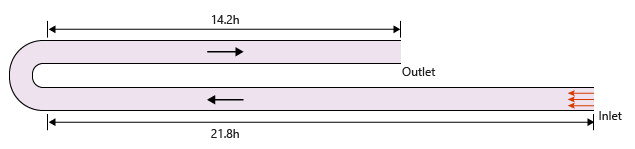
Figure 1. Critical Dimensions and Parameters for Simulating Turbulent Flow in the 180 degree U-Duct
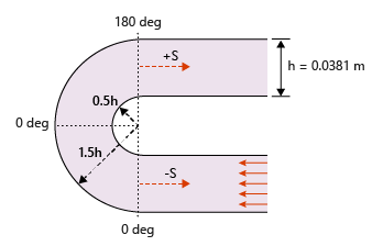
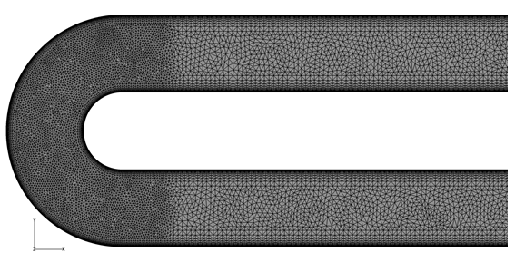
Figure 2. Mesh Used for Simulating Turbulent Flow in the 180 Degree U-Duct
AcuSolve Results
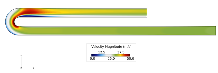
Figure 3. Velocity Contours in Stream Wise Plane
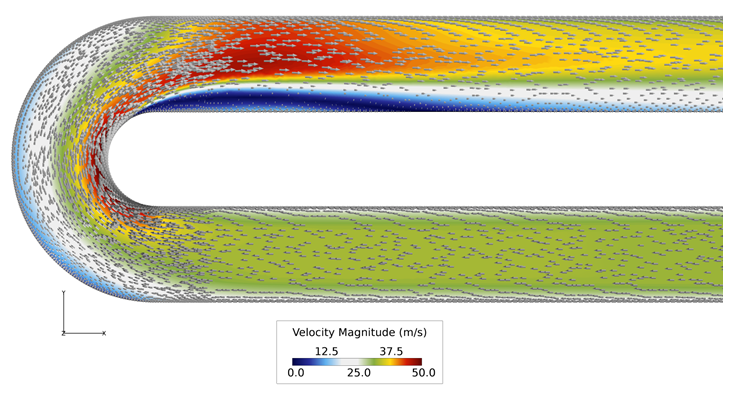
Figure 4. Close up View of Velocity Vectors and Velocity Contours at 180 Degree Bend

Figure 5.
Summary
The AcuSolve solution compares well with experimental results for flow past the 180 degree U-duct. The experimental value for the ratio of Velocity magnitude to inlet bulk velocity at different sections of the U-duct is presented with the corresponding AcuSolve result for various turbulence models. The performance of the Spalart Allmaras turbulence model was found to improve when the rotation curvature correction is included in the numerical formulation. In this application, AcuSolve demonstrates the ability to predict the complex boundary layer separation and reattachment resulting from the curvature of the channel.
Simulation Settings for Turbulent Flow Through a 180 Degree Curved Channel
AcuConsole database file: <your working directory>\curved_channel_simple_turbulent\curved_channel_simple_turbulent.acs
Global
- Problem Description
- Analysis type - Steady State
- Turbulence equation - Spalart Allmaras
- Auto Solution Strategy
- Relaxation factor - 0.4
- Material Model
- Air
- Type- Constant
- Density- 1.0 kg/m3
- Viscosity- 1.1818e-006 kg/m-sec
Model
- Air
- Volumes
- Fluid
- Element Set
- Material model- Air
- Element Set
- Fluid
- Surfaces
- Inlet
- Simple Boundary Condition
- Type- Wall
- Inflow type- Velocity
- Inflow velocity type- Normal
- Normal velocity- 31.1 m/sec
- Turbulence input type- Direct
- Eddy viscosity- 3.5547e-06 m2/sec
- Simple Boundary Condition
- ext1
- Simple Boundary Condition- Symmetry
- ext2
- Simple Boundary Condition- Symmetry
- Outlet
- Simple Boundary Condition
- Type- Outflow
- Simple Boundary Condition
- wall-bottom
- Simple Boundary Condition
- Type- Wall
- Turbulence wall type- Low Reynolds Number
- Simple Boundary Condition
- wall-top
- Simple Boundary Condition
- Type- Wall
- Turbulence wall type- Low Reynolds Number
- Simple Boundary Condition
- Inlet
References
Christopher L. Rumsey, Thomas B. Gatski, and Joseph H. Morrison. "Turbulence Model Predictions of Strongly Curved Flow in a U-Duct", AIAA Journal, Vol. 38, No. 8 (2000), pp. 1394-1402.